
Automatic tightening device for double-ended studs and assembly line for double-ended studs of automobile engines

A technology of automatic tightening device and automobile engine, applied in metal processing equipment, metal processing, manufacturing tools, etc., can solve the problems of unable to meet the requirements of automobile production line assembly, single working mode, etc., to improve the automation rate of the whole line and reduce labor , The effect of stable pressing force

Active Publication Date: 2021-01-01
嘉兴希力工业科技有限公司
View PDF1 Cites 0 Cited by
  • Summary
  • Abstract
  • Description
  • Claims
  • Application Information

AI Technical Summary

Problems solved by technology

The utility model is an automatic tightening device for double-ended studs and nuts, which is used for automatic tightening of batches of double-ended studs or nuts regularly distributed on slender workpieces, which not only ensures the reliability, precision and anti-interference ability of the tightening system , can also improve the tightening consistency and tightening efficiency, but the problem is that the working mode is single and cannot meet the assembly requirements of the automobile production line

Method used


Image

  • Automatic tightening device for double-ended studs and assembly line for double-ended studs of automobile engines
  • Automatic tightening device for double-ended studs and assembly line for double-ended studs of automobile engines
  • Automatic tightening device for double-ended studs and assembly line for double-ended studs of automobile engines

Examples


Embodiment Construction

[0042] In order to make the purpose, technical solutions and advantages of this application clearer, the technical solutions in the embodiments will be clearly and completely described below in conjunction with the accompanying drawings in the embodiments. Obviously, the described embodiments are only a part of the application Examples, not all examples. Based on the given embodiments, all other embodiments obtained by persons of ordinary skill in the art without creative efforts fall within the protection scope of the present application.

[0043] In the description of the present application, it should be understood that the orientation or positional relationship indicated by the terms "upper", "lower" and the like is based on the orientation or positional relationship shown in the drawings, and is only for the convenience of describing the present application and simplifying the description, It is not intended to indicate or imply that the device or element referred to must...


PUM


Abstract

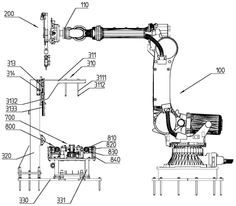
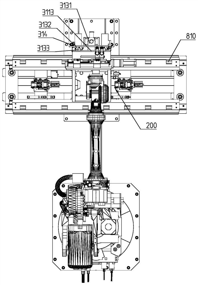
The invention discloses a double-end stud automatic tightening device. The double-end stud automatic tightening device comprises a mechanical arm and a tightening device body, and the tightening device body is fixedly arranged on the mechanical arm and is switched between a double-end bolt clamping position and a double-end bolt tightening position along with rotation of the mechanical arm. The tightening device body comprises at least two tightening electric shafts arranged side by side, double-end bolt clamping sleeves and a tightening electric shaft relative position adjusting mechanism. The double-end bolt clamping sleeves are connected to the output ends of the corresponding tightening electric shafts. At least one tightening electric shaft is fixedly arranged at the output end of thetightening electric shaft relative position adjusting mechanism and conducts translation along with reciprocating movement of the output end of the tightening electric shaft relative position adjusting mechanism to change the distance between the adjacent tightening electric shafts. The double-end stud automatic tightening device further comprises a conveying line, a stopper, a jacking mechanismand a pressing mechanism, wherein the stopper is located in the double-end bolt tightening position and used for stopping an engine from moving along the conveying line continuously; the jacking mechanism is used for jacking up the engine vertically after the stopper stops the engine and forcing the engine to get away from the conveying line; and the pressing mechanism presses down to clamp and position the engine.

Description

technical field [0001] The invention belongs to the technical field of special machines for assembly lines of automobile engines, and in particular relates to an automatic tightening device for double-ended studs and an assembly line for double-ended studs of automobile engines. Background technique [0002] Double-ended studs refer to cylindrical fasteners with threads at both ends, which are widely used in electric power, chemical industry, oil refining, valves, railways, bridges, steel structures, automobile and motorcycle parts, machinery, boiler steel structures, hanging towers, large Span steel structures and large buildings, etc. The double-ended stud connection is to screw one end of the double-ended stud into the screw hole of one of the connected parts, and the other end passes through the through hole of the other connected part, then put on the washer and tighten the nut. [0003] At present, more than 99% of the double-ended studs of the engine exhaust manifold...

Claims


Application Information

Patent Timeline
Patent Type & Authority Patents(China)
IPC IPC(8): B23P19/06
CPCB23P19/06
Inventor 邱恩水王颖峰程志国唐瑞波洪浩祯
Owner 嘉兴希力工业科技有限公司
Learn More