
Contact conduction structure for relay

A relay and conduction technology, applied in the direction of relays, electromagnetic relays, detailed information of electromagnetic relays, etc., can solve the problems of low conduction installation efficiency, loose relay cables and conductive terminals, and failure to use normally, so as to improve conduction Installation efficiency and the effect of improving conduction yield

Pending Publication Date: 2019-10-08
SANYOU CORP LTD
View PDF0 Cites 0 Cited by
  • Summary
  • Abstract
  • Description
  • Claims
  • Application Information

AI Technical Summary

Problems solved by technology

[0002] The relay is one of the commonly used accessories of various intelligent control equipment. The relay includes an insulating base and a conductive terminal installed on the insulating base. During the manufacturing process of the relay, the conductive terminal needs to be connected with other conductors. In the prior art The main reason is that the conductive terminal and the conductor are welded together by soldering, and the efficiency of the conduction installation is low; in addition, when the conductive terminal and the conductor are separated by accident, the disconnection of the conductive terminal and the conductor will cause the relay to fail to work normally
[0003] In addition, the relay needs to be used to connect two conductive terminals with a cable. In the prior art, the connection between the cable and the conductive terminals is not firm, and the relay often cannot be used normally because the cable and the conductive terminals are loose.

Method used


Image

  • Contact conduction structure for relay
  • Contact conduction structure for relay
  • Contact conduction structure for relay

Examples


Embodiment Construction

[0032] In order to facilitate the understanding of those skilled in the art, the present invention will be further described below in conjunction with the embodiments and accompanying drawings, and the contents mentioned in the implementation modes are not intended to limit the present invention.

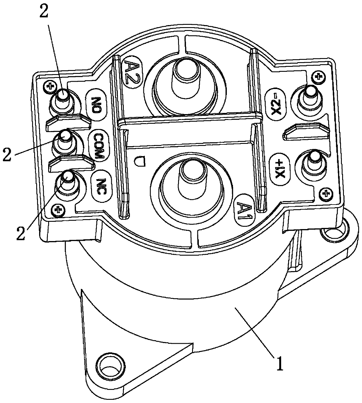
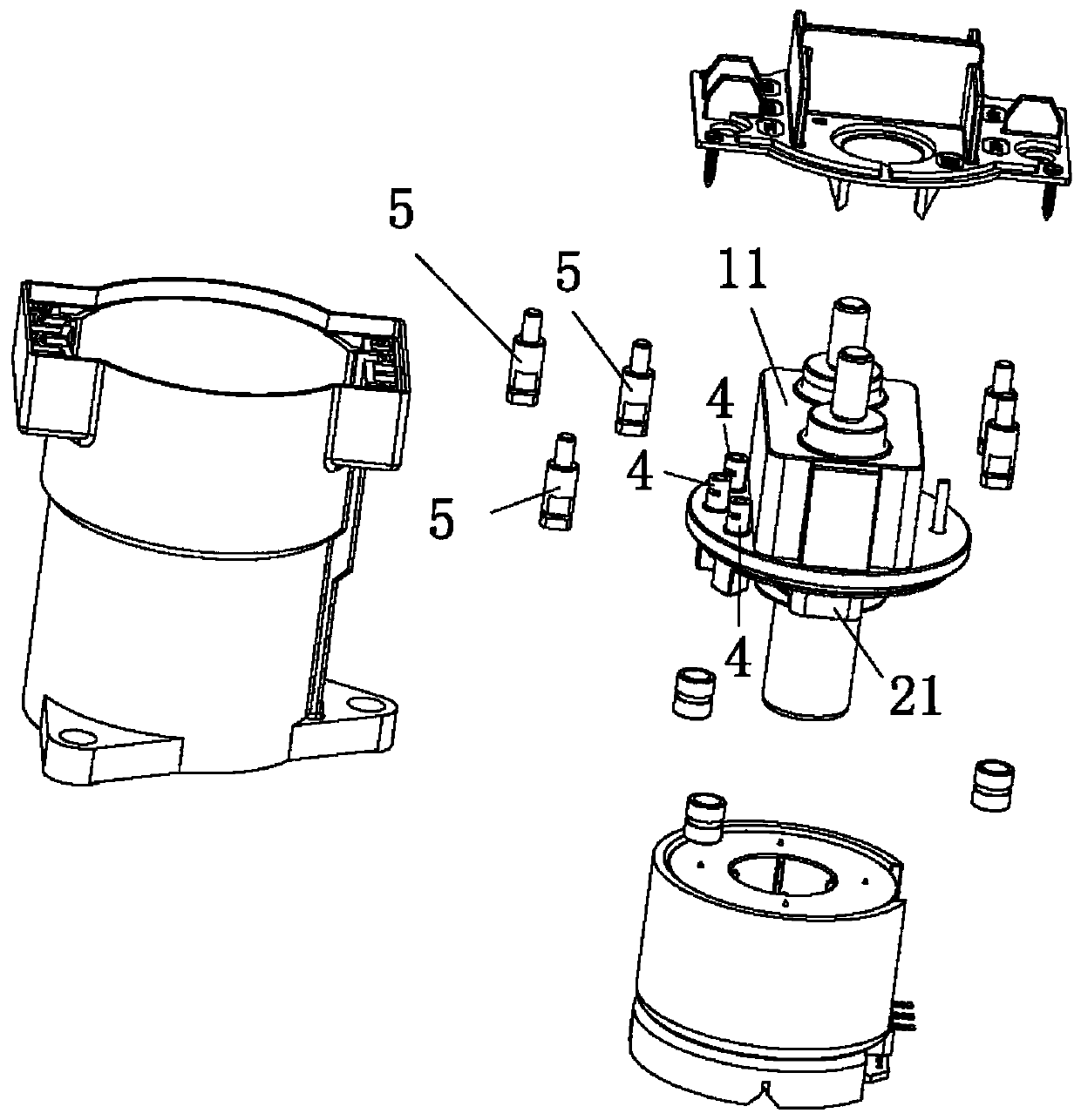
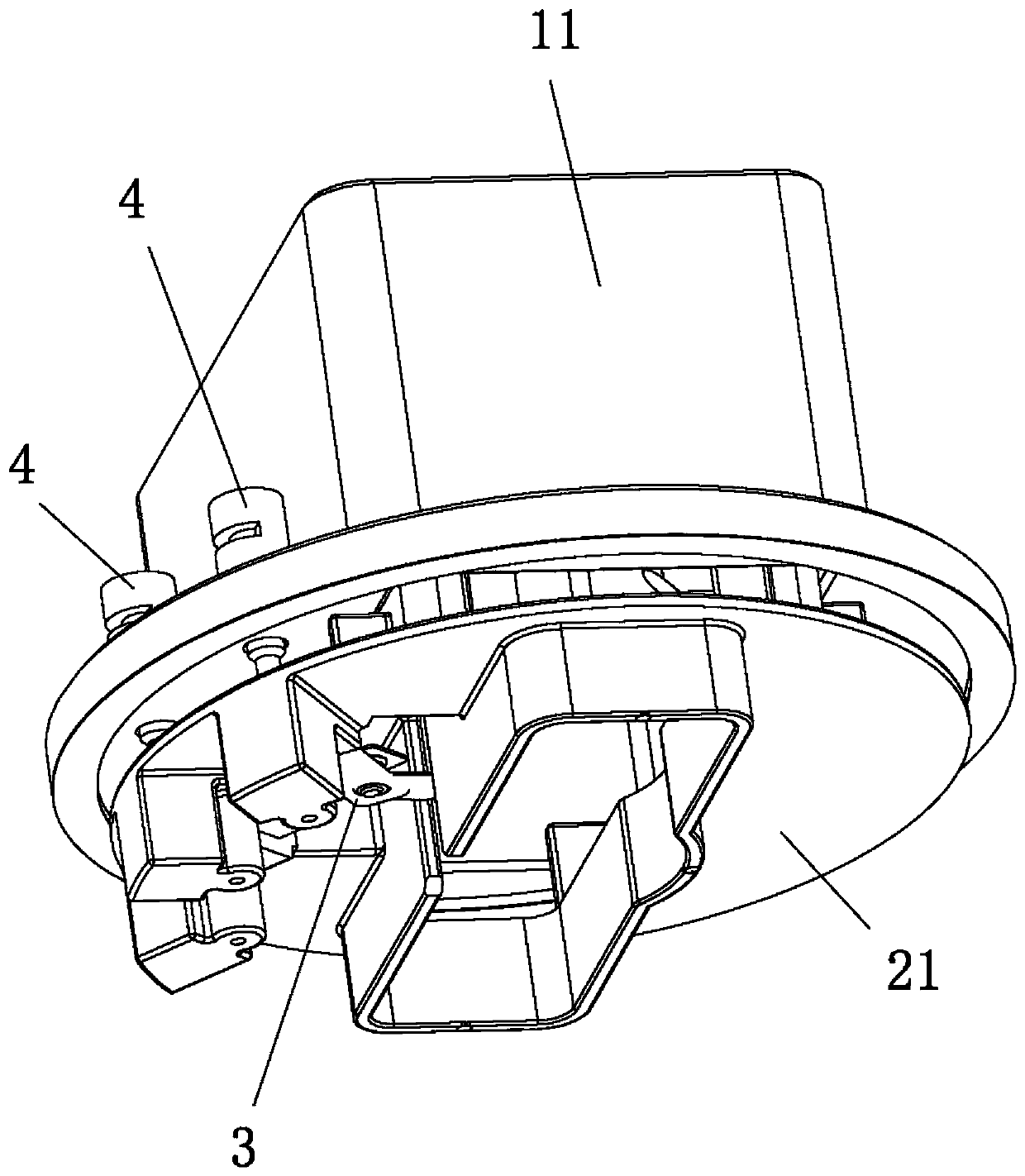
[0033] see Figure 1 to Figure 5 As shown, a contact conduction structure for a relay of the present invention includes a relay body 1 and a contact assembly 2 arranged on the relay body 1. The contact assembly 2 includes a conductive sheet 3, a first terminal 4, a second Two terminals 5 and wires (not shown in the figure), the conductive sheet 3 is made of conductive material, the conductive sheet 3 is connected to the first terminal 4, and the first terminal 4 is connected to the second terminal 5 via the wire.

[0034] The conductive sheet 3 is provided with an elastic clip 6 for clamping and conducting the first terminal 4, and the first terminal 4 is clamped by the elastic defo...


PUM


Abstract

The invention relates to the technical field of relays, in particular to a contact conduction structure for a relay. The contact conduction structure comprises a relay body and a contact assembly arranged on the relay body. The contact assembly comprises a conductive sheet, a first terminal, a second terminal and a lead. The conductive sheet and the first terminal are conducted. The first terminalis conducted with the second terminal via the lead. The conductive sheet is provided with an elastic clip. The first terminal or / and the second terminal is / are provided with a first recess hole and asecond recess hole communicated with the first recess hole. The first terminal is clamped by the elastic clip for conduction in actual use with no requirement for welding of the conductive sheet andthe first terminal so that the conduction mounting efficiency of the conductive sheet and the first terminal can be enhanced. The lead is accommodated in the first recess hole, and external solder enters the first recess hole through the second recess hole to weld the lead on the terminal so as to ensure that the lead and the terminal are stably welded together and improve the conduction yield between the first terminal and the second terminal.

Description

technical field [0001] The invention relates to the technical field of relays, and in particular discloses a contact conduction structure for relays. Background technique [0002] The relay is one of the commonly used accessories of various intelligent control equipment. The relay includes an insulating base and a conductive terminal installed on the insulating base. During the manufacturing process of the relay, the conductive terminal needs to be connected with other conductors. In the prior art The main reason is that the conductive terminal and the conductor are welded together by soldering, and the efficiency of the conduction installation is low; in addition, when the conductive terminal and the conductor are accidentally separated, the disconnection of the conductive terminal and the conductor will cause the relay to fail to work normally. [0003] In addition, the relay needs to be used to connect two conductive terminals with a cable. In the prior art, the connectio...

Claims


Application Information

Patent Timeline
Patent Type & Authority Applications(China)
IPC IPC(8): H01H50/54
CPCH01H50/54
Inventor 唐俊平
Owner SANYOU CORP LTD
Learn More