
damper

A technology of damper and damper shaft, which is applied in the direction of shock absorber, shock absorber, liquid shock absorber, etc., can solve the problem that the damping force output control curve cannot maintain linearity, and achieve the effect of increasing the output adjustment range

Inactive Publication Date: 2020-02-07
YANGTZE UNIV COLLEGE OF TECH & ENG
View PDF13 Cites 0 Cited by
  • Summary
  • Abstract
  • Description
  • Claims
  • Application Information

AI Technical Summary

Problems solved by technology

Chinese patent document CN107324144A describes a tension adjustment device, which can adjust the width with a large damping force, but the installation method of this scheme can only maintain the structure of the vertical axis, and is affected by factors such as eddy currents and evaporation, and the damping force is limited. Output control curve fails to maintain linearity

Method used


Image

  • damper
  • damper
  • damper

Examples


Embodiment Construction

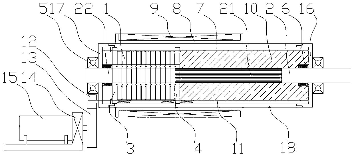
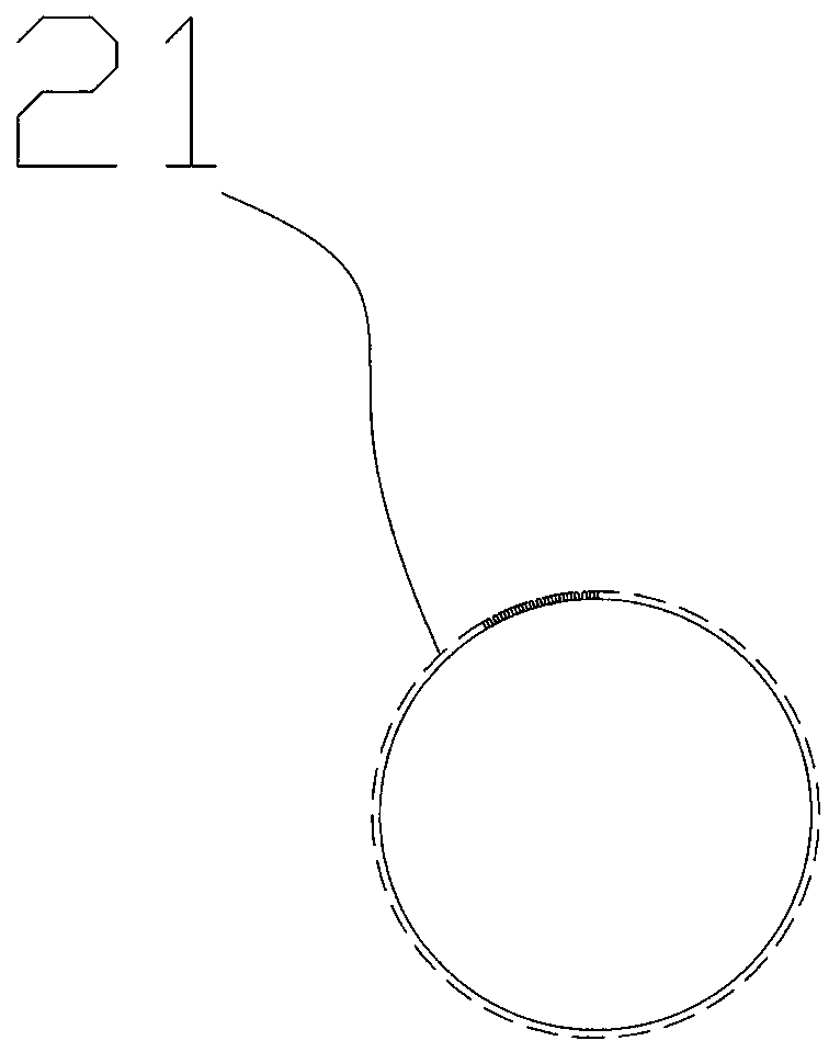
[0029] Such as Figure 1~3 Among them, a damper, a liquid medium 10 is provided in a sealed housing 18, a rotatable damping shaft 2 is provided in the sealed housing 18, the damping shaft 2 is slidingly connected with the damping plate 1, and the damping shaft 2 is provided with There are a toothed section 21 and a smooth section 22, and the outer wall of the toothed section 21 is provided with a plurality of teeth;

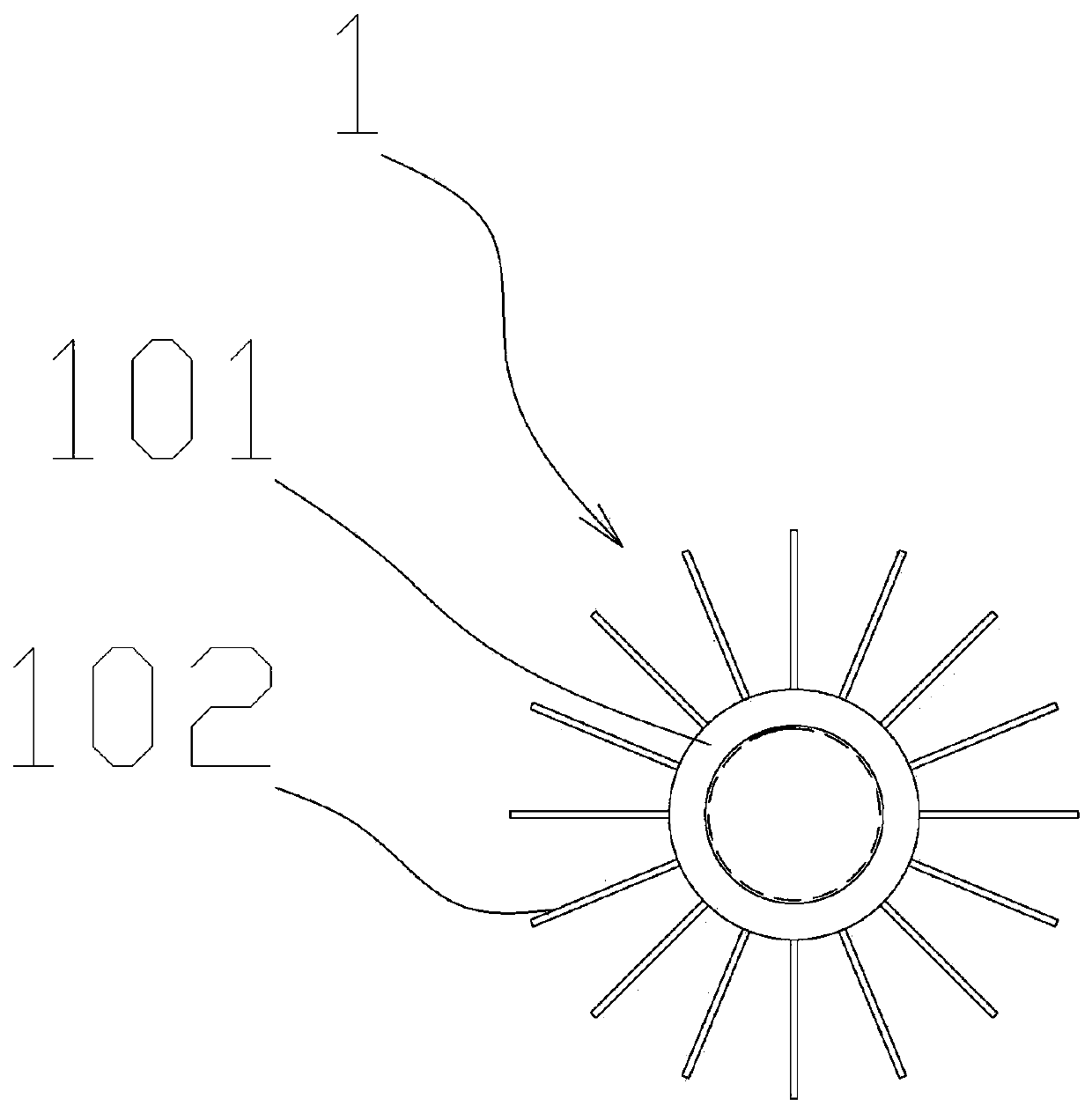
[0030] The damping sheet 1 includes a transmission ring 101 and a plurality of blades 102, the plurality of blades 102 are radially fixed on the outer wall of the transmission ring 101, and are uniformly distributed along the circumference, and the inner wall of the transmission ring 101 is provided with a plurality of blades that engage with the toothed segment 21. teeth;

[0031] The damping plate 1 and the toothed segment 21 of the damping shaft 2 are engaged and disengaged to adjust the magnitude of damping. With this structure, through the damping plate 1 ...


PUM


Abstract

The invention provides a damper. A liquid medium is arranged in a sealed shell, a rotatable damping shaft is arranged in the sealed shell, a damping shaft is in sliding connection with damping fins, atoothed section and a smooth section are arranged on the damping shaft, and a plurality of teeth are arranged on the outer wall of the toothed section; each damping fin comprises a transmission ringand a plurality of blades, the multiple blades are fixedly arranged on the outer walls of the transmission rings in a radial mode, and the multiple teeth meshed with the toothed section are arranged on the inner walls of the transmission rings; and the damping fins and the toothed section of the damping shaft are meshed and separated to adjust the size of the damping. By the mode that resistance is generated between the damping fins and the liquid medium, a smooth and adjustable damping force is obtained.

Description

technical field [0001] The invention relates to the field of dampers, in particular to a damper with adjustable damping force. Background technique [0002] Known dampers commonly used in spinning or wire production usually use electromagnetic control of the damping force, such as an electromagnetic damper recorded in Chinese patent document CN201590744U, by adjusting the magnitude of the current, the torque can be adjusted size, but this adjustment method has the problem of nonlinear control curve, that is, within the wide range of adjustment, it is difficult to obtain a linear output curve for the damping force, and due to structural limitations, mainly due to the limitations of the structure of each magnetic head, the output of the damping force fluctuates . In the high-precision production process, this tension fluctuation will affect the quality of the product. In addition, Chinese patent literature also records a CN1258654C magnetron friction damper, which generates ...

Claims


Application Information

Patent Timeline
Patent Type & Authority Patents(China)
IPC IPC(8): F16F9/12F16F9/44F16F9/53
CPCF16F9/125F16F9/44F16F9/535
Inventor 马秀花
Owner YANGTZE UNIV COLLEGE OF TECH & ENG
Learn More