Power transmission device

A technology of power transmission and heat conduction, applied in transmission, fluid transmission, transmission control, etc., can solve problems such as lock-up clutch damage

Inactive Publication Date: 2019-10-08
EXEDY CORP
View PDF1 Cites 0 Cited by
  • Summary
  • Abstract
  • Description
  • Claims
  • Application Information

AI Technical Summary

Problems solved by technology

However, if such slip control is performed, there will be a problem of damage due to overheating of the friction material of the lock-up clutch

Method used


Image

  • Power transmission device
  • Power transmission device
  • Power transmission device

Examples


Embodiment Construction

[0027] Embodiments of the power transmission device according to the present invention will be described below with reference to the drawings.

[0028] [the whole frame]

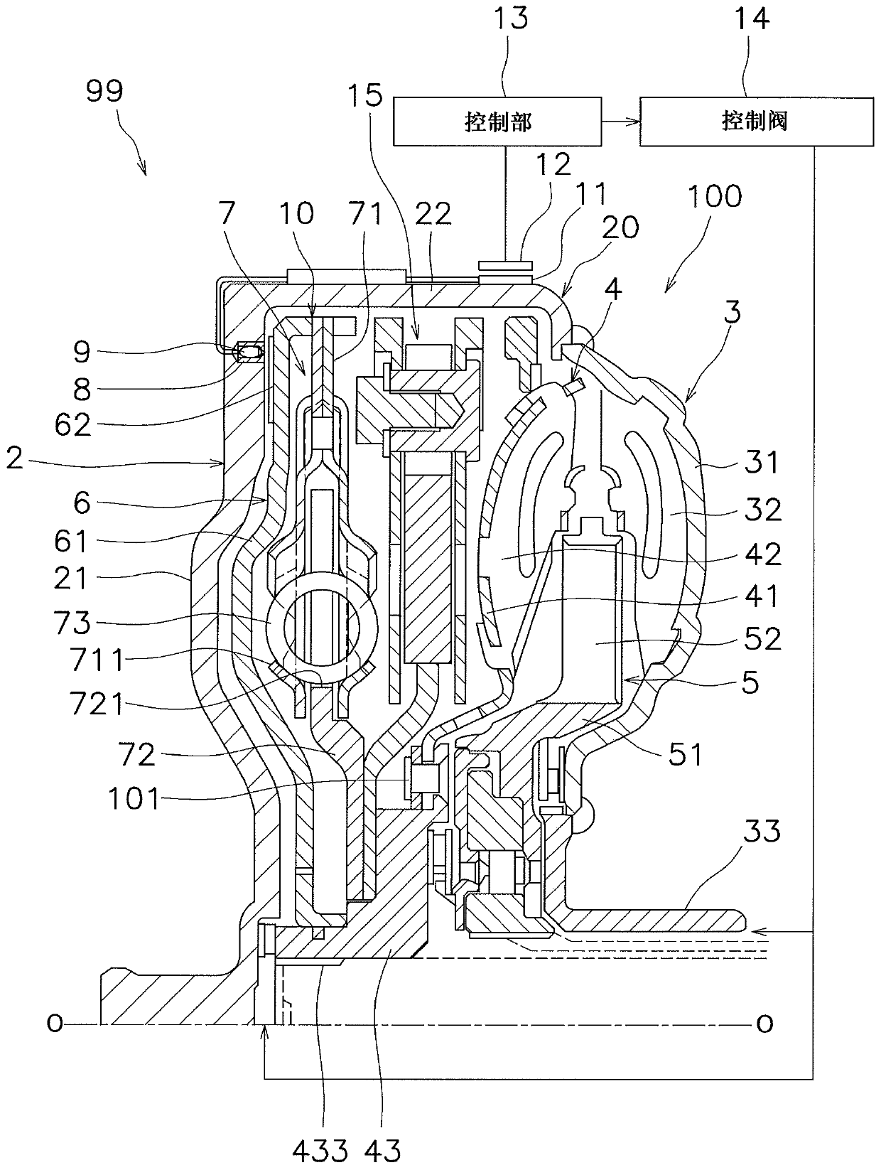
[0029] figure 1 It is a cross-sectional view of a power transmission device 99 according to an embodiment of the present invention. The power transmission device 99 includes a torque converter 100 . In the following description, "axial direction" refers to the direction in which the rotation axis O of the torque converter 100 extends. In addition, "circumferential direction" refers to the circumferential direction of a circle centering on the rotation axis O, and "radial direction" refers to the radial direction of a circle centering on the rotation axis O. The radially inner side refers to the side closer to the rotation axis O in the radial direction, and the radial outer side refers to the side away from the rotation axis O in the radial direction. In addition, although not shown, in the figure 1 The...


PUM


Abstract

A power transmission device is disclosed. The power transmission device includes a housing, a clutch unit, a heat conducting unit, and a heat conducting unit. The housing includes a wall portion. Thehousing is rotatably disposed, with the torque from the drive source being transmitted to the housing. The wall portion has a through hole formed therein. The clutch unit includes a friction surface engageable with the housing and disposed opposite to the through hole. The clutch unit is disposed in the housing so as to be rotatable relative to the housing. The heat conducting unit is disposed inthe through hole and exposed in the housing. The temperature detecting unit is configured to detect a temperature of the heat conducting unit.

Description

technical field [0001] The invention relates to a power transmission device. Background technique [0002] The power transmission device includes a housing that is rotated by torque from a drive source, and a lock-up clutch that is rotatable relative to the housing within the housing. For example, a torque converter has a front cover, an impeller, a turbine, and a lock-up clutch. The casing is constituted by the front cover and the impeller casing. In a region where the number of rotations of the driving source per unit time (hereinafter simply referred to as the number of rotations) is low, the lock-up clutch is disengaged, and the torque from the driving source is output through the impeller and the turbine. In addition, when the predetermined number of revolutions is exceeded, the lock-up clutch is engaged and frictionally engaged with the front cover. This enables output of torque from the drive source through the lock-up clutch. [0003] In recent years, in order to...

Claims


Application Information

Patent Timeline
Patent Type & Authority Applications(China)
IPC IPC(8): F16D66/00F16H61/14
CPCF16D66/00F16D2066/008F16H61/14F16H61/12F16H2045/0205F16H2045/0215F16H2045/0221F16H2045/0278F16H2061/1232F16H2061/1276F16H2061/145F16H41/30F16H45/02F16H61/143
Inventor 安田圭一
Owner EXEDY CORP
Why Eureka
Try Eureka