


Quick Research
Generate reliable direction feasibility study reports for your R&D in just a few steps.

Technical Q&A
Discover and master advanced knowledge NOW. Basics, ideas, possibilities, all at once.

Find Solutions
As an expert in R&D theories, this can generate solutions to your technical problems instantly.

Evaluate Feasibility
Analyze your overall solution with one click, know your potential R&D risks in advance.

Monitor Landscape
Get weekly tech updates, stay abreast of the latest tech innovations and key insights.
Apparatus and method for simulating and visualizing fracture seepage by using magnetic fluid
A magnetic fluid and fissure technology, applied in the field of rock fissure test, can solve the problems of lack of test equipment and methods, and achieve clear and reliable pictures
- Summary
- Abstract
- Description
- Claims
- Application Information
AI Technical Summary
Problems solved by technology
Method used
Image

Examples
Embodiment 1
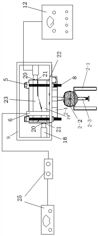
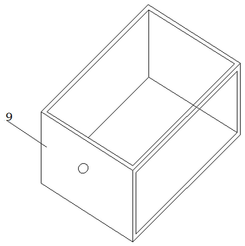
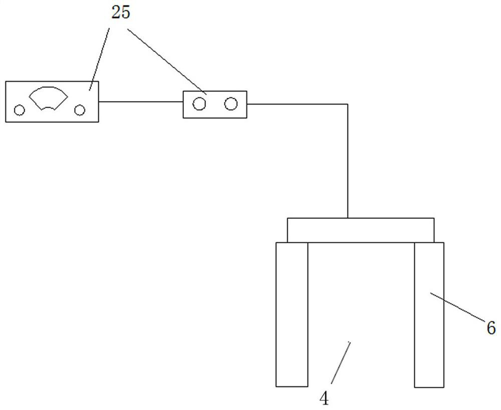
[0030] like Figure 1-Figure 4 As shown in the figure, a device for visualizing seepage flow in cracks by using magnetic fluid simulation includes a main frame 1, a retractable support rod is arranged on the main frame 1, and a movable sub-frame 10 is slidably connected to the top surface of the main frame 1, and is installed on the main frame 1 The camera 7 inside is connected with the movable sub-frame 10 through the top universal spherical hinge 11 on the main frame 1, and the shear reaction force frame 9 is installed on the bottom plate 1-1 of the main frame 1 through the universal spherical hinge reaction force device 2 On the surface, the visualized rock sample 26 is placed on the upper surface of the shearing reaction force frame 9 through the inflated and pressurized air cushion 22, and the inflated and pressurized air cushion 22 is communicated with the inflatable device 24. Composition, a crack is formed between the transparent resin 23 of the upper cover plate and t...
Embodiment 2
[0037] A method for simulating and visualizing seepage flow through the above-mentioned device, the method comprises the following steps:
[0038] Step 1: Adjust the angle of the top universal spherical hinge 11 so that the camera 7 is perpendicular to the top surface of the visualized rock sample 26;
[0039] Step 2: Adjust the height of the retractable support rod, and place the camera 7 in a suitable position (can clearly capture and visualize the seepage situation without reflection, ghosting, etc., which affect the later experimental data processing);
[0040]Step 3: Inject gas into the expanded pressurized air cushion 22 through the inflation device 24 (use the pressure gauge on the high-pressure nitrogen cylinder to adjust the pressure), and adjust the normal stress on the visualized rock sample 26;
[0041] Step 4: Turn on the shear loading device 18, and control the magnitude of the shear force by adjusting the thrust of the hydraulic rod. The magnitude of the shear f...
Embodiment 3
[0045] In the above-mentioned embodiment 1, the preparation method of the visualized rock sample 26 is as follows:
[0046] Step a: Prepare rock crack surface: collect rocks with natural joint cracks (including opposite surfaces) or split a block of rock to obtain a split surface, the size of which depends on the test requirements;
[0047] Step b: Prepare the test silica gel according to the mass ratio of hardener and liquid silica gel at 1:50, pour the liquid silica gel evenly on the cracked surface of the rock sample to be simulated, wait for it to solidify and harden after 3 hours, and take it out. Down;
[0048] Step c: prepare transparent resin: get a certain amount of liquid resin in a suitable container, first add a promoter with a mass content of 0.6%-0.8% and stir for 2 minutes, and then add a mass content of 0.6%-0.8% Hardener, stir for 2 minutes, and finally add a defoamer with a mass content of 0.6%-1.2%, stir slowly for 2 minutes, and the whole process should be...
PUM
| Property | Measurement | Unit |
|---|---|---|
| thickness | aaaaa | aaaaa |
Abstract
Description
Claims
Application Information
 - R&D Engineer
- R&D Manager
- IP Professional
- Industry Leading Data Capabilities
- Powerful AI technology
- Patent DNA Extraction
Browse by: Latest US Patents, China's latest patents, Technical Efficacy Thesaurus, Application Domain, Technology Topic, Popular Technical Reports.
© 2024 PatSnap. All rights reserved.Legal|Privacy policy|Modern Slavery Act Transparency Statement|Sitemap|About US| Contact US: help@patsnap.com