A gripping structure and gripping method of a robot manipulator

A technology of manipulators and robots, applied in the field of robotics, can solve the problems of excessive opening angle of the mechanical claws, inability to adjust the position of the mechanical claws of the manipulator, and easy clamping instability, etc., to achieve a firm grasping effect

Active Publication Date: 2021-05-28
NANJING YUSHENG ROBOT CO LTD
View PDF0 Cites 0 Cited by
  • Summary
  • Abstract
  • Description
  • Claims
  • Application Information

AI Technical Summary

Problems solved by technology

[0003] The object of the present invention is to provide a gripping structure of a robot manipulator to solve the problem that the size of the existing manipulator proposed in the above background technology is often fixed, and it is impossible to adjust the position of the mechanical claw of the manipulator, and can only grip a certain size. When encountering relatively large workpieces, the mechanical claws need to open a large angle to grab the workpiece. Because the opening angle of the mechanical claws is too large, it is easy to clamp unstable problems

Method used


Image

  • A gripping structure and gripping method of a robot manipulator
  • A gripping structure and gripping method of a robot manipulator
  • A gripping structure and gripping method of a robot manipulator

Examples


Embodiment 1

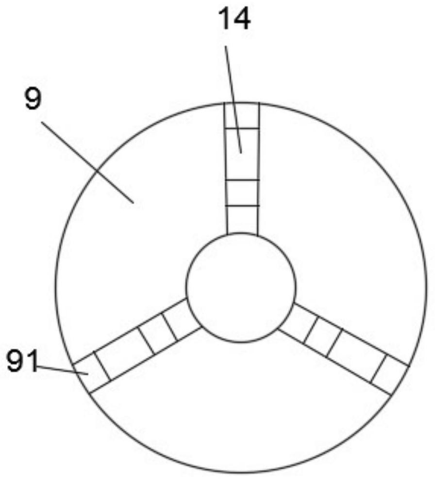
[0040] see Figure 1-7, this embodiment provides a gripping structure of a robot manipulator, including a housing 1, a mounting base 2 fixedly mounted on the housing 1, and a mechanical claw 8 mounted on the housing 1, wherein the mounting base 2 is provided with threading holes and bolt holes for installation, a motor 3 is fixedly installed on the top of the housing 1, the motor 3 is a servo motor, and a chuck 9, a turntable 10 and a chuck seat 11 are installed inside the housing 1, The turntable 10 is rotatably installed between the chuck 9 and the chuck seat 11, wherein the chuck 9 is fixedly installed with the housing 1, and the turntable 10 is rotatably installed with the casing 1, so that the turntable 10 can rotate inside the casing 1, The chuck seat 11 is fixedly connected with the housing 1 by bolts, the chuck 9 is slidably mounted with a block 14 that can slide outwards, the block 14 is slidably mounted with a slider 15, and on the slider 15 The first rotating shaft...

Embodiment 2

[0048] see Figure 7-13 , on the basis of Embodiment 1, a further improvement is made: the two sides of the block 14 are provided with a clip chute 143 that matches the clip 93, and the side away from the gear groove 144 is provided with a clip that matches the clip 93. The chute 143 is parallel to the T-shaped slideway 141, the inside of the T-shaped slideway 141 is rotatably equipped with a second screw 142, and the top of the second screw 142 is provided with a hexagon socket bolt hole for adjustment; Block 15 is provided with T-shaped slide block 152 in the same body near clamping block 14, and T-shaped slide block 152 matches with T-shaped slideway 141, and T-shaped slide block 152 and T-shaped slideway 141 can prevent slide block 15 from following the first step. The second screw rod 142 rotates to limit the slider 15, and the second screw rod 142 runs through the T-shaped slider 152 and is rotatably connected with the T-shaped slider 152. The rotation of the second scre...


PUM


Abstract

The invention discloses a gripping structure and a gripping method of a robot manipulator, comprising a housing and a mechanical claw mounted on the housing, a motor is fixedly installed on the top of the housing, a chuck, The turntable and the chuck seat, the chuck is slidably mounted with a block that can slide outward, the block is slidably mounted with a slider, the slider is rotatably mounted with a first shaft, and the mechanical claw The top is rotatably installed with the first rotating shaft, a bracket is fixedly installed in the center of the chuck, a sliding disc is slidably installed on the outside of the bracket, and a support bar is installed on the outer side of the sliding disc, and the support bar is far away from the side of the sliding disc. One end is rotated and installed with the inner side of the mechanical claw. The invention facilitates the adjustment of the mechanical claw. At the same time, the opening angle of the mechanical claw can always be in the triangular pyramid structure with a large opening at the top and a small opening at the bottom, making the gripping of workpieces more stable and firm.

Description

technical field [0001] The invention relates to the technical field of robots, in particular to a gripping structure of a robot manipulator. Background technique [0002] With the development of industrialization and intelligence, manipulators have been used more and more in production. The size of existing manipulators is often fixed, and it is impossible to adjust the position of the mechanical claws of the manipulator. It can only grip a certain size. When encountering relatively large workpieces, the mechanical claws need to open a large angle to grab the workpiece. Because the opening angle of the mechanical claws is too large, it is easy to clamp unstable problems. Contents of the invention [0003] The purpose of the present invention is to provide a gripping structure of a robot manipulator to solve the problem that the size of the existing manipulator proposed in the above background technology is often fixed, and the position of the mechanical claw of the manipul...

Claims


Application Information

Patent Timeline
Patent Type & Authority Patents(China)
IPC IPC(8): B25J15/10B25J15/02
CPCB25J15/0206B25J15/10
Inventor 沈虹袁凯
Owner NANJING YUSHENG ROBOT CO LTD
Why Eureka
Try Eureka