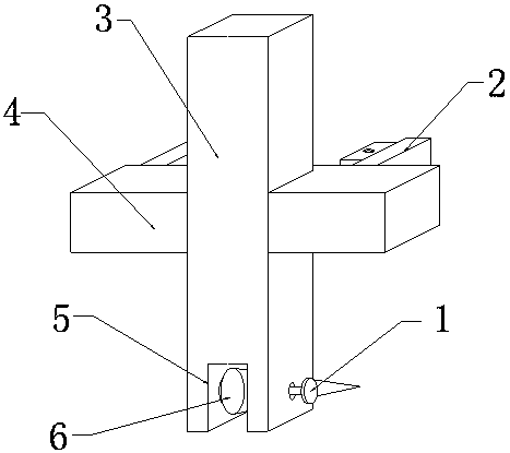
Lineation pin for machining of numerical control milling machine
A technology of CNC milling machine and scribing pin, applied in the field of CNC machine tools, can solve the problems of difficult operation, inability to quickly install the scribing needle, inconvenient installation of the scribing needle, etc., and achieve the effect of easy operation.
- Summary
- Abstract
- Description
- Claims
- Application Information
AI Technical Summary
Problems solved by technology
Method used
Image


Examples
specific Embodiment approach
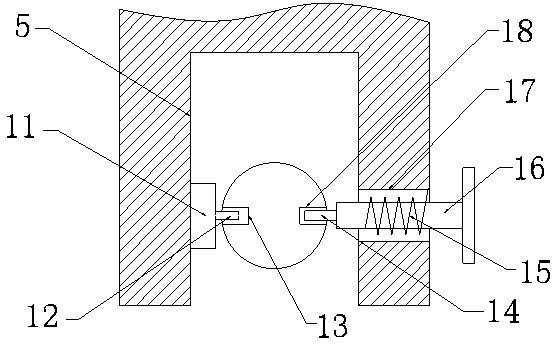
[0022] Specific implementation method: when in use, the operator pulls the push handle to the right, and the push handle drives the push rod 16 to move to the right in the guide hole 17, and the push rod 16 moves to squeeze the spring 15, causing the spring 15 to deform, and then the needle body 6 The clamping hole 13 on the top is snapped into the positioning pin 12, and then the push handle is released, and then the spring 15 pushes the push rod 16 to move to the left under the action of the rebound force, and the push rod 16 moves to the left to drive the bayonet pin 14 to move to the left. And the bayonet pin 14 is pushed into the bayonet 2 18, and then the positioning pin 12 and the bayonet pin 14 fix the stylus body 6 in the bayonet 5, thereby realizing the quick installation function of the stylus body 6, which is convenient for operators to operate.
[0023] Then the operator closely fits the right magnetic seat 25 on the device to the right end face of the CNC milling ...
PUM
 Abstract
Description
Claims
Application Information
 - R&D
- Intellectual Property
- Life Sciences
- Materials
- Tech Scout
- Unparalleled Data Quality
- Higher Quality Content
- 60% Fewer Hallucinations
Browse by: Latest US Patents, China's latest patents, Technical Efficacy Thesaurus, Application Domain, Technology Topic, Popular Technical Reports.
© 2025 PatSnap. All rights reserved.Legal|Privacy policy|Modern Slavery Act Transparency Statement|Sitemap|About US| Contact US: help@patsnap.com