
Building concrete damage detection equipment

A technology for damage detection and concrete, applied in the direction of measuring devices, applying stable tension/pressure to test the strength of materials, instruments, etc., can solve the problems of small size, troublesome and time-consuming, and difficult to find the sheath, so as to avoid difficult to find Effect

Inactive Publication Date: 2019-09-27
湖州华科建设工程质量检测有限公司
View PDF0 Cites 0 Cited by
  • Summary
  • Abstract
  • Description
  • Claims
  • Application Information

AI Technical Summary

Problems solved by technology

[0003] However, at present, there are many concretes that are often shoddy, and their strength is not satisfactory, especially in some national key construction projects, the requirements for concrete strength standards are very high, so it is necessary and necessary to test the strength of concrete. The commonly used concrete strength testing techniques in my country are divided into non-destructive testing and micro-damage testing. The pull-off method strength testing technology improved by micro-damage testing in the existing technology mainly uses the correlation between concrete tensile strength and compressive strength to detect, infer The compressive strength of concrete structures or components, the three-jaw chuck, as the main gripping tool, needs to be stored in a dry and dust-free environment after use, while the three-jaw chuck in the prior art is exposed on the outer surface of the protective shell In the storage, the three-jaw chuck needs to be cleaned first and then put on the sheath. For cleaning and maintenance, only a soft dry cloth can be used or the dry cloth should be soaked in clean water and wrung out before removing dust and dirt. Some The groove wall deep inside is difficult to clean, which is not only troublesome but also time-consuming, and the sheath is often difficult to find due to its small size

Method used


Image

  • Building concrete damage detection equipment
  • Building concrete damage detection equipment
  • Building concrete damage detection equipment

Examples


Embodiment

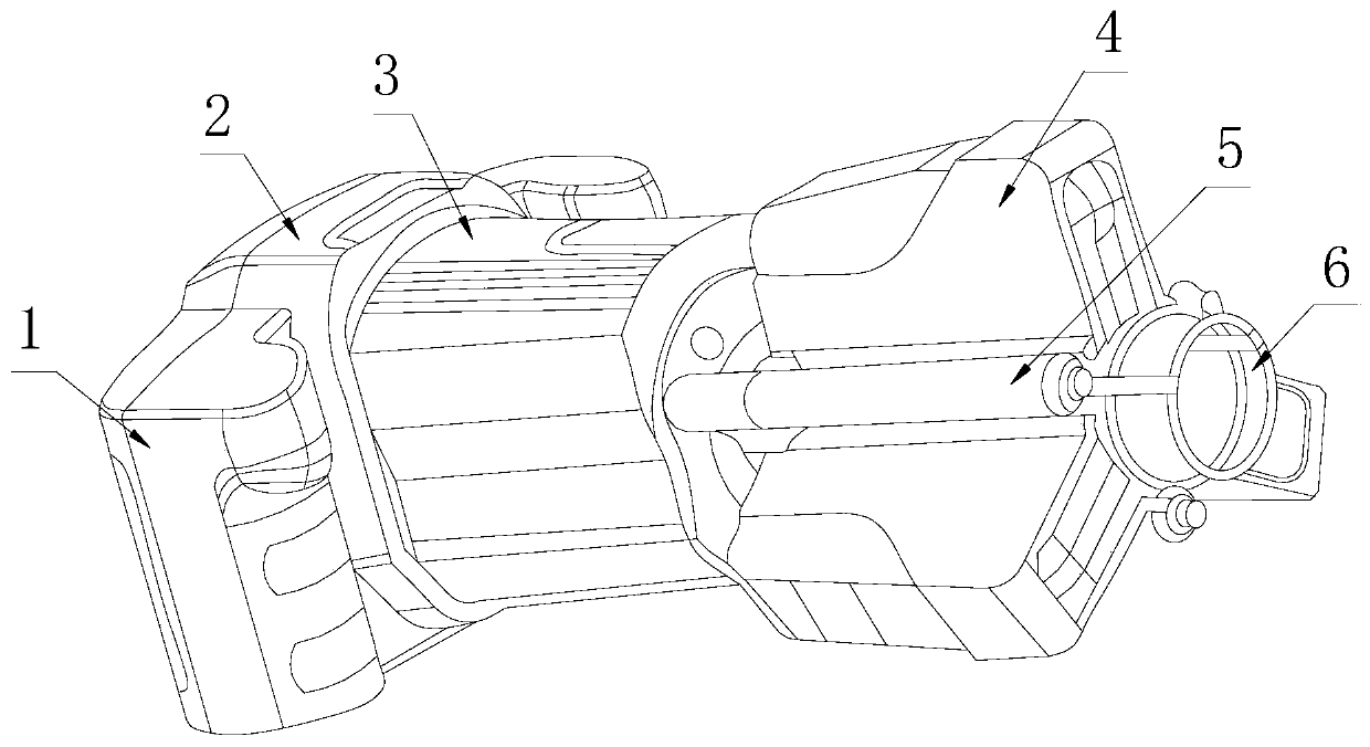
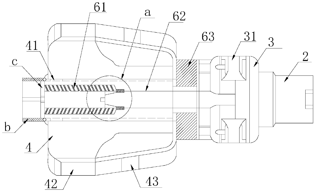
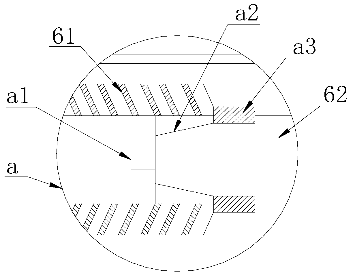
[0027] Such as Figure 1-Figure 4 As shown, the present invention provides a kind of building concrete damage detection equipment, and its structure comprises handle 1, data collector 2, reduction box 3, protective shell 4, support bar 5, three-jaw chuck 6, and the data collector 2 The outer surface is fixed with a handle 1, the data collector 2 is electrically connected to the reduction box 3, the three-jaw chuck 6 is controlled by the reduction box 3, and the three-jaw chuck 6 is matched inside the protective shell 4 , a support rod 5 is fixed in the crack of the protective shell 4, a rotating sleeve 63 is movably fitted at the junction of the reduction box 3 and the three-jaw chuck 6, and the main screw is respectively installed in the level of the three-jaw head 6 62 and the auxiliary screw 61, a locking mechanism a is matched at the contact port of the auxiliary screw 61 and the main screw 62, the end of the auxiliary screw 61 relative to the main screw 62 is fixed with t...


PUM


Abstract

The invention discloses building concrete damage detection equipment that structurally comprises a handle, a data collector, a reduction gearbox, a protective shell, a supporting rod and a three-jaw chuck; the handle is fixed on the outer surface of the data collector; the data collector is electrically connected with the reduction gearbox; the three-jaw chuck is controlled by a reduction gearbox; the three-jaw chuck is arranged in the protective shell in a matched mode. The supporting rod is fixed in a crack of the protective shell; a rotary sleeve is movably matched at the joint of the reduction gearbox and the three-jaw chuck; a main screw rod is driven by the rotary sleeve; a rotating mechanism formed by mutual meshing of an auxiliary screw rod and the main screw rod is matched with the three-jaw chuck to realize telescopic access; when the three-jaw chuck is not used or after the three-jaw chuck is used, the three-jaw chuck stretches into rod cavities of the main screw rod and the auxiliary screw rod in a spiral mode; the three-jaw chuck can be directly contained in the protective shell without protection of a protective sleeve; the three-jaw chuck is more portable compared with protective sleeve protection, and the problem that the protective sleeve is difficult to find can also be avoided.

Description

technical field [0001] The invention relates to the technical field of construction, in particular to a construction concrete damage detection device. Background technique [0002] Concrete is an indispensable material in the construction process of construction projects. At this stage and for a long time in the future, the economy and applicability of concrete materials are incomparable to many other materials. [0003] However, at present, there are many concretes that are often shoddy, and their strength is not satisfactory, especially in some national key construction projects, the requirements for concrete strength standards are very high, so it is necessary and necessary to test the strength of concrete. The commonly used concrete strength testing techniques in my country are divided into non-destructive testing and micro-damage testing. The pull-off method strength testing technology improved by micro-damage testing in the existing technology mainly uses the correlatio...

Claims


Application Information

Patent Timeline
IPC IPC(8): G01N3/08G01N3/04
CPCG01N3/04G01N3/08G01N2203/0017G01N2203/0067G01N2203/0274G01N2203/04
Inventor 郑亮朱嘉亿
Owner 湖州华科建设工程质量检测有限公司
Learn More