
A steel strip shearing and clamping device

A steel belt and clamping block technology, applied in shearing devices, accessories of shearing machines, chucks, etc., can solve problems such as hidden safety hazards, low work efficiency, manual dismantling, etc., to achieve automatic operation and improve work efficiency. , the effect of increasing enterprise efficiency

Active Publication Date: 2020-07-10
NORTHEASTERN UNIV LIAONING
View PDF11 Cites 0 Cited by
  • Summary
  • Abstract
  • Description
  • Claims
  • Application Information

AI Technical Summary

Problems solved by technology

[0002] At present, the unbundling of steel coils in iron and steel enterprises is mainly done manually, which requires a lot of manpower and material resources, and the work efficiency is low
And because the steel belt has a certain degree of elasticity, there are potential safety hazards in the process of manual unbundling
However, the existing steel strip shearing and clamping device has large dimensions, complex structure, slow strip removal speed, and requires two or more power sources to complete the shearing and clamping process, which cannot meet the increasingly accelerated production line and safety requirements. Work requirements

Method used


Image

  • A steel strip shearing and clamping device
  • A steel strip shearing and clamping device
  • A steel strip shearing and clamping device

Examples


Embodiment Construction

[0028] The present invention will be further described below in conjunction with the accompanying drawings and specific embodiments.

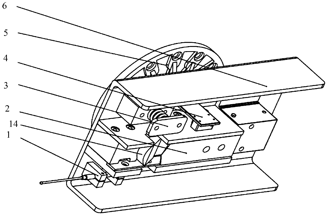
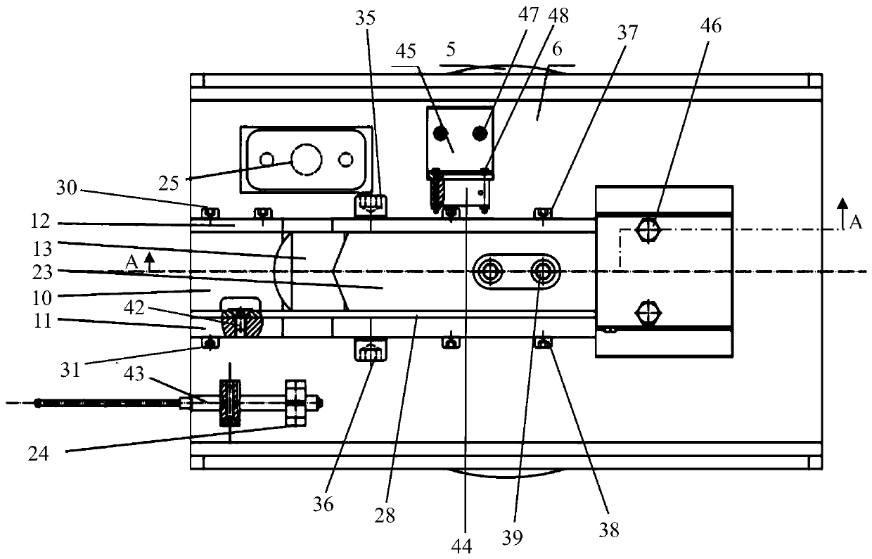
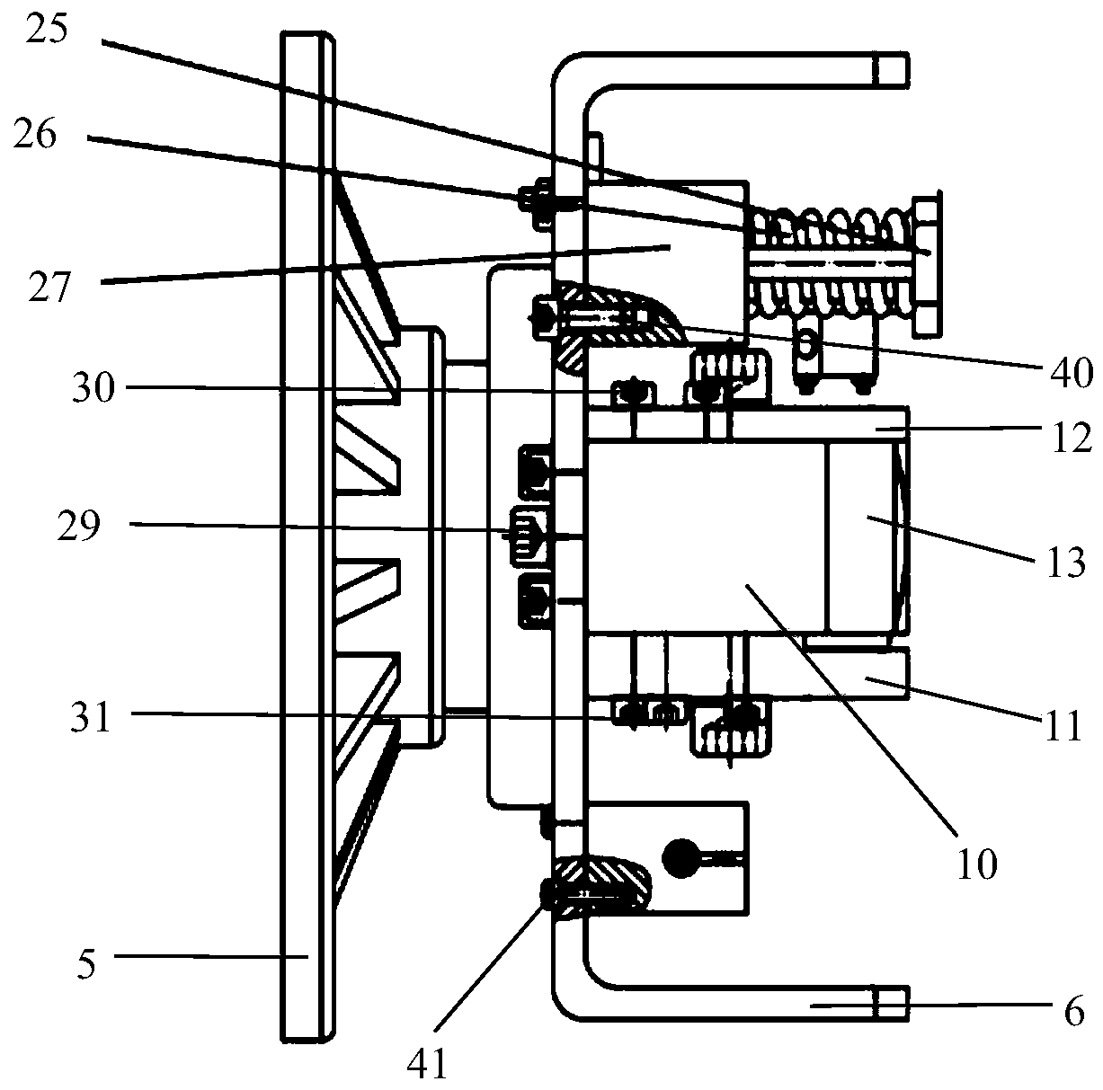
[0029] Such as figure 1 , figure 2 , image 3 Shown are the structural schematic diagram, front view, and left side view of the steel strip shearing and gripping device of the present invention, respectively. figure 2 The A-A sectional view is as follows Figure 4 shown. The steel strip shearing and gripping device of the present invention is characterized in that it includes a manipulator connecting flange 5 , an installation base 6 , a shearing and gripping module 2 , a compression module 3 , a linear displacement sensor module 1 , and a laser displacement sensor module 4 .

[0030] The manipulator connecting flange 5 is connected to the end of the manipulator of the industrial robot through a plurality of first screws 7 ; the installation base 6 is connected to the manipulator connecting flange 5 through second screws 8 and a plurality...


PUM


Abstract

The invention relates to the technical field of steel belt shearing and clamping and provides a steel belt shearing and clamping device. The device comprises a mechanical hand connecting flange, an installation base, a shearing and clamping module, a pressing module, a linear displacement sensor module and a laser displacement sensor module. The mechanical hand connecting flange is connected with the tail end of a mechanical hand of an industrial robot. The shearing and clamping module comprises a first side plate, a second side plate, a first side plate fixing block, a second side plate fixing block, a clamping module, an upper shear blade, a shoveling blade, a shoveling blade connecting sliding block, a sliding rail, a hydraulic cylinder and a hydraulic cylinder installation base. The clamping module comprises a clamping block, a second compression spring, a clamping block base and a clamping block guiding plate. A reversing control valve coil of the hydraulic cylinder, the linear displacement sensor and the laser displacement sensor are electrically connected with a single-chip microcomputer. The single-chip microcomputer is electrically connected with a controller of the industrial robot. By means of the steel belt shearing and clamping device, automatic operation of steel belt shearing and clamping can be achieved, and the work efficiency, the work safety and the work quality are improved.

Description

technical field [0001] The invention relates to the technical field of steel strip shearing and clamping, in particular to a steel strip shearing and clamping device. Background technique [0002] At present, the unbundling of steel coils in iron and steel enterprises is mainly done manually, which requires a lot of manpower and material resources, and the work efficiency is low. And because the steel strip has certain elasticity, there is a potential safety hazard in the process of manually unbundling. However, the existing steel strip shearing and clamping device has large dimensions, complex structure, slow strip removal speed, and requires two or more power sources to complete the shearing and clamping process, which cannot meet the increasingly accelerated production line and safety requirements. Work requirements. Contents of the invention [0003] Aiming at the problems existing in the prior art, the present invention provides a steel strip shearing and clamping d...

Claims


Application Information

Patent Timeline
Patent Type & Authority Patents(China)
IPC IPC(8): B23D31/00B23D33/00B25J15/00B25J19/02
CPCB23D31/00B23D31/002B23D33/00B25J15/00B25J19/02
Inventor 刘宇胡国权
Owner NORTHEASTERN UNIV LIAONING
Learn More