LED control method and system, cooking appliance
A control method and technology for cooking utensils, applied to cooking utensils, timing control ignition mechanisms, kitchen utensils, etc., can solve the problem of large instantaneous current, reduce the instantaneous current, reduce the instantaneous maximum current, and reduce the requirements of power supply and chip Effect
- Summary
- Abstract
- Description
- Claims
- Application Information
AI Technical Summary
Problems solved by technology
Method used
Image
Examples
Embodiment 1
[0037] According to an embodiment of the present invention, an embodiment of an LED control method is provided. It should be noted that the steps shown in the flowcharts of the accompanying drawings can be executed in a computer system such as a set of computer-executable instructions, and, although A logical order is shown in the flowcharts, but in some cases the steps shown or described may be performed in an order different from that shown or described herein.
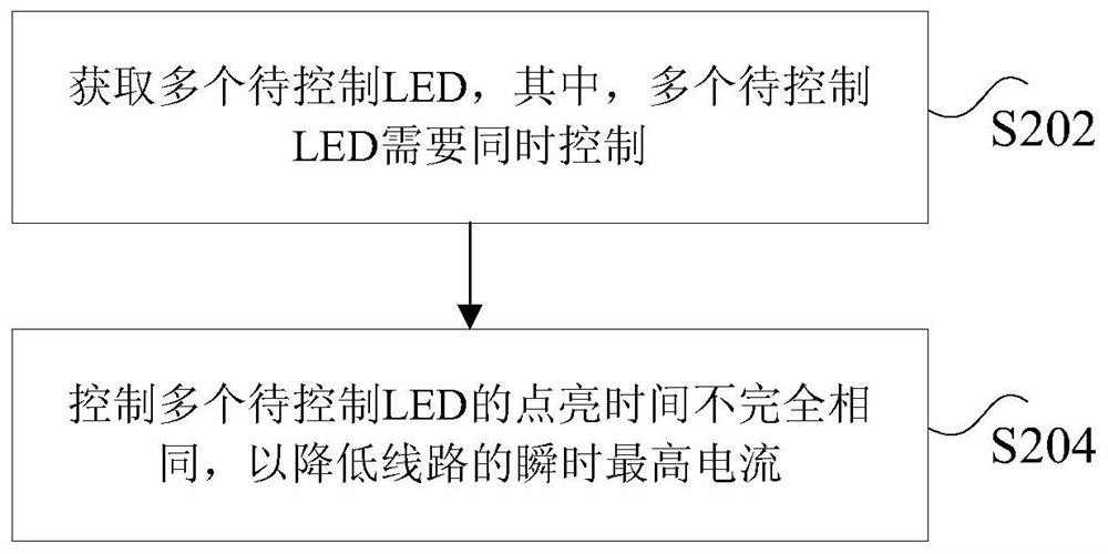
[0038] figure 2 is a flow chart of an LED control method according to an embodiment of the present invention, such as figure 2 As shown, the method includes the following steps:
[0039] Step S202, obtaining a plurality of LEDs to be controlled, wherein the plurality of LEDs to be controlled need to be controlled simultaneously.
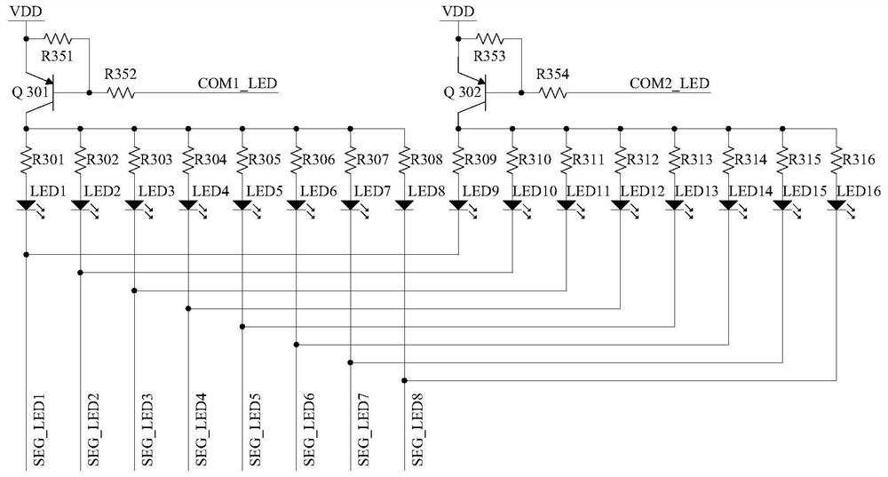
[0040] Specifically, such as figure 1 As shown, the aforementioned plurality of LEDs to be controlled may be any number of LED1 to LED16, for example, may be LED1-LED8.
[0041] Step...
Embodiment 2
[0074] According to an embodiment of the present invention, an embodiment of an LED control system is provided.
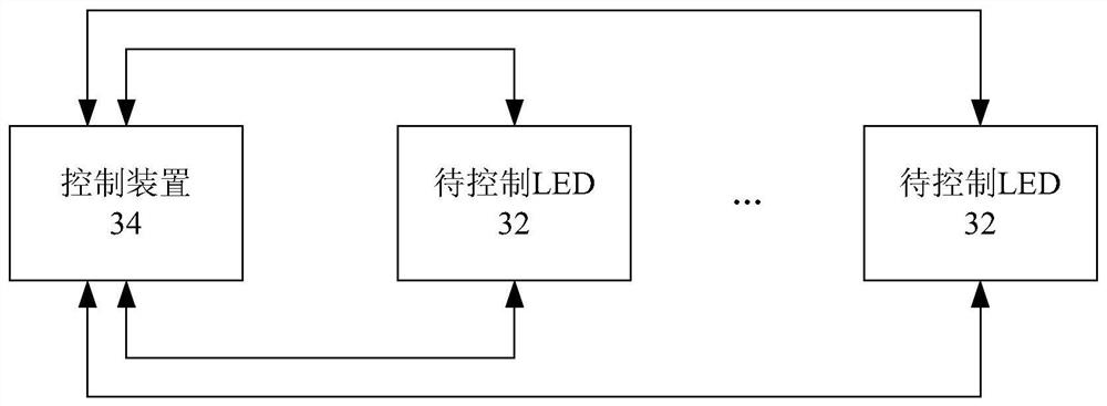
[0075] image 3 is a schematic diagram of an LED control system according to an embodiment of the present invention, such as image 3 As shown, the system includes: a plurality of LEDs 32 to be controlled and a control device 34 .
[0076] Wherein, the control device is connected to a plurality of LEDs to be controlled, and is used to control the lighting time of the plurality of LEDs to be controlled to be different, so as to reduce the instantaneous maximum current of the circuit.
[0077] Specifically, such as figure 1 As shown, the aforementioned plurality of LEDs to be controlled may be any number of LED1 to LED16, for example, may be LED1-LED8. By changing the lighting time and order of the LEDs, the lighting time of multiple LEDs to be controlled is staggered, thereby reducing the number of LEDs that are lit at the same time, and reducing the instantaneou...
Embodiment 3
[0089] According to an embodiment of the present invention, an embodiment of a cooking appliance is provided, including: the LED control system in Embodiment 2 above.
[0090] Optionally, the above-mentioned cooking appliance is an electric pressure cooker.
[0091] Specifically, the above-mentioned cooking appliance may be an appliance such as an electric pressure cooker, an electric rice cooker, or a cooking machine that needs to display and control LEDs. In the embodiment of the present invention, an electric pressure cooker is used as an example for illustration.
PUM
 Abstract
Description
Claims
Application Information
 - Generate Ideas
- Intellectual Property
- Life Sciences
- Materials
- Tech Scout
- Unparalleled Data Quality
- Higher Quality Content
- 60% Fewer Hallucinations
Browse by: Latest US Patents, China's latest patents, Technical Efficacy Thesaurus, Application Domain, Technology Topic, Popular Technical Reports.
© 2025 PatSnap. All rights reserved.Legal|Privacy policy|Modern Slavery Act Transparency Statement|Sitemap|About US| Contact US: help@patsnap.com


