Storage cabinet based on FPGA control and object storage and fetching method

A technology of lockers and cabinets, which is applied in the field of fetching, FPGA-based lockers and storage, and can solve the problem of increasing the burden on users to carry unlocked items

Active Publication Date: 2019-09-20
HARBIN INST OF TECH SHENZHEN GRADUATE SCHOOL
View PDF6 Cites 0 Cited by
  • Summary
  • Abstract
  • Description
  • Claims
  • Application Information

AI Technical Summary

Problems solved by technology

Both mechanical lock lockers and barcode lockers require users to carry corresponding unlocking items. For example, mechanical lock lockers need to carry keys, while barcode lockers need to carry barcodes. Although it provides users with the convenience of storing items, but at the same time However, it increases the burden on users to carry unlocked items, and cannot provide users with the convenience of not having to carry items

Method used


Image

  • Storage cabinet based on FPGA control and object storage and fetching method
  • Storage cabinet based on FPGA control and object storage and fetching method
  • Storage cabinet based on FPGA control and object storage and fetching method

Examples


Embodiment 1

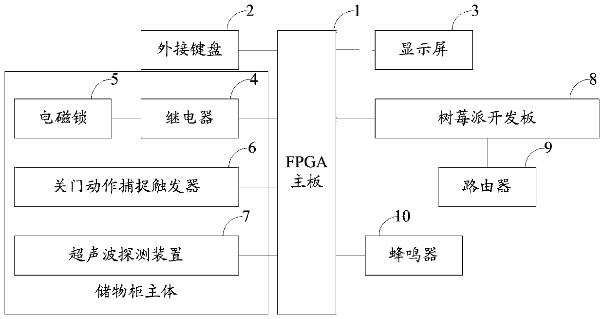
[0058] figure 1 It is a device connection diagram of the locker based on FPGA control in Embodiment 1 of the present invention.

[0059] see figure 1 , the locker based on FPGA control includes: an FPGA main board 1, an external keyboard 2, a display screen 3 and a plurality of locker main bodies; the locker main body includes a relay 4, an electromagnetic lock 5, and a door closing motion capture trigger 6 and ultrasonic detection device 7.

[0060] The output end of each described door-closing action capture trigger 6 is all connected with the input end of described FPGA mainboard 1; The output end of described FPGA mainboard 1 is connected with each described relay 4, and each described relay 4 is connected in corresponding In the circuit where the electromagnetic lock 5 is located; the FPGA main board 1 is connected with the ultrasonic detection device 7 bidirectional communication; the output end of the external keyboard 2 is connected with the input end of the FPGA mai...

Embodiment 2

[0096] Embodiment 2 discloses a storage method based on an FPGA-controlled locker, which is applied to the FPGA-controlled locker in Embodiment 1.

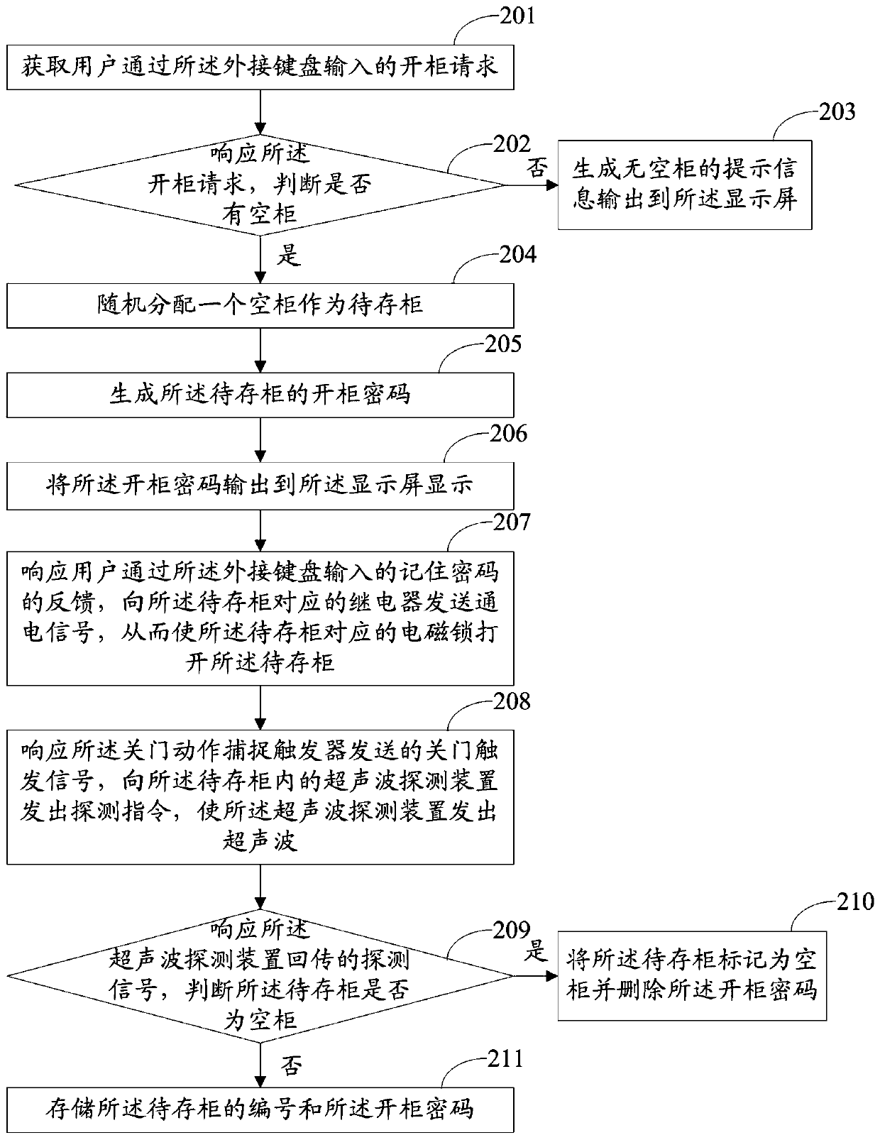
[0097] figure 2 It is a method flow chart of the storage method of the locker based on FPGA control according to Embodiment 2 of the present invention.

[0098] see figure 2 , the deposit method includes:

[0099] Step 201: Obtain the cabinet opening request input by the user through the external keyboard;

[0100] Step 202: responding to the cabinet opening request, judging whether there is an empty cabinet, and obtaining a first judging result;

[0101] Step 203: If the first judgment result indicates no, generate a prompt message that there are no empty cabinets and output it to the display screen;

[0102] Step 204: If the first judgment result indicates yes, randomly assign an empty cabinet as the cabinet to be stored;

[0103] Step 205: Generate the password for opening the cabinet to be stored;

[0104] Step 206: Ou...

Embodiment 3

[0120] Embodiment 3 discloses an FPGA-controlled locker retrieval method, which is applied to the FPGA-controlled locker in Embodiment 1. The fetching method of this embodiment 3 is corresponding to the storage method of embodiment 2.

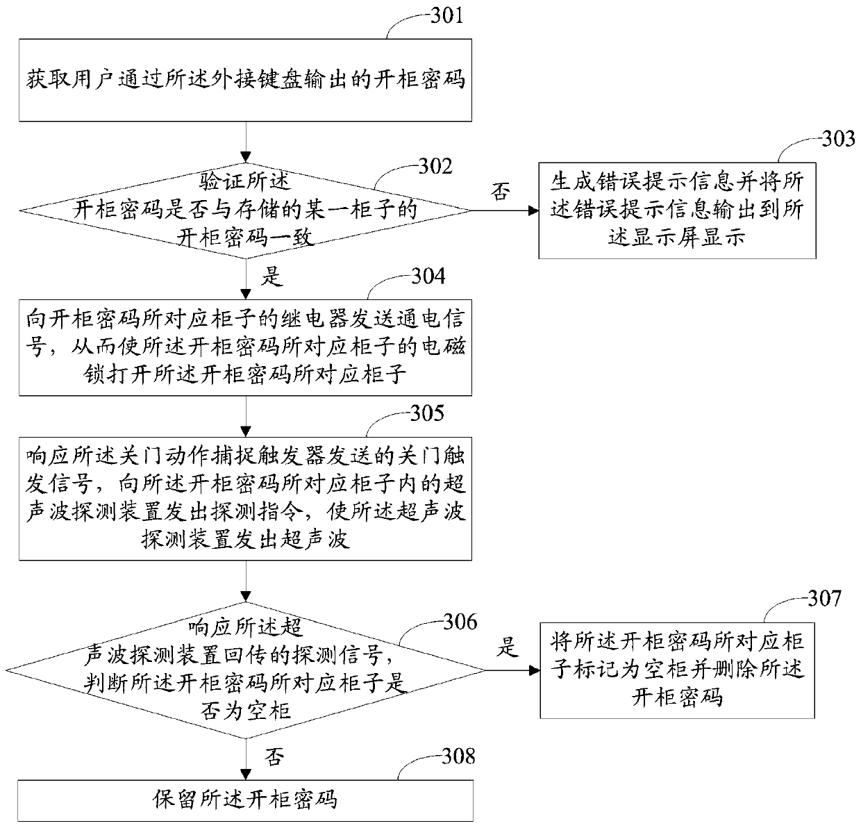
[0121] image 3 It is a method flow chart of the FPGA-controlled locker retrieval method according to Embodiment 2 of the present invention.

[0122] see image 3 , the extraction method includes:

[0123] Step 301: Obtain the cabinet opening password output by the user through the external keyboard;

[0124] Step 302: verify whether the password for opening the cabinet is consistent with the stored password for opening a certain cabinet, and obtain a third judgment result;

[0125] Step 303: If the third judgment result indicates no, generate error prompt information and output the error prompt information to the display screen for display;

[0126] Step 304: If the third judgment result indicates yes, then send an energization signal to ...


PUM


Abstract

The invention discloses a storage cabinet based on FPGA control and an object storage and fetching method. The storage cabinet comprises: an FPGA mainboard, an external keyboard, a display screen and a plurality of storage cabinet main bodies; each storage cabinet main body comprises a relay, an electromagnetic lock, a door closing motion capture trigger and an ultrasonic detection device. The output ends of the door closing motion capture triggers are connected with the input end of the FPGA mainboard; the output end of the FPGA mainboard is connected with the relays, the relays are connected in the loops where the corresponding electromagnetic locks are located; the FPGA mainboard is in bidirectional communication connection with the ultrasonic detection device; the output end of the external keyboard is connected with the input end of the FPGA mainboard, and the output end of the FPGA mainboard is connected with the input end of the display screen; the FPGA mainboard is used for generating a cabinet opening password, controlling to open a cabinet door, determining whether the cabinet is an empty cabinet or not and verifying whether the password is correct or not. According to the invention, a user does not need to carry any unlocking article after storing the article.

Description

technical field [0001] The invention relates to the field of public lockers, in particular to a locker based on FPGA control and a method for depositing and fetching objects. Background technique [0002] With the development of the social public service industry, shopping malls, schools, libraries and other places need a lot of storage to facilitate people's temporary placement of personal items. Existing lockers include mechanical lock lockers and barcode lockers. Both mechanical lock lockers and barcode lockers require users to carry corresponding unlocking items. For example, mechanical lock lockers need to carry keys, while barcode lockers need to carry barcodes. Although it provides users with the convenience of storing items, but at the same time However, it increases the burden on the user to carry the unlocked item, and cannot provide the user with the convenience of not having to carry the item. Contents of the invention [0003] The object of the present inven...

Claims


Application Information

Patent Timeline
Patent Type & Authority Applications(China)
IPC IPC(8): G07F17/12
CPCG07F17/12
Inventor 肖安琪刘俊武陈筱雯李昕阳李奕辉李佳琪薛瑞
Owner HARBIN INST OF TECH SHENZHEN GRADUATE SCHOOL
Why Eureka
Try Eureka