
Sine driving method of permanent magnet synchronous motor

A technology of permanent magnet synchronous motor and driving method, applied in motor control, AC motor control, electrical components, etc.

Inactive Publication Date: 2019-09-17
BEIJING INSTITUTE OF TECHNOLOGYGY
View PDF4 Cites 2 Cited by
  • Summary
  • Abstract
  • Description
  • Claims
  • Application Information

AI Technical Summary

Problems solved by technology

The method of obtaining the corresponding phase current reference value directly from the Hall output is not suitable for the situation where there is an angle deviation between the sensor and the coil

Method used


Image

  • Sine driving method of permanent magnet synchronous motor
  • Sine driving method of permanent magnet synchronous motor
  • Sine driving method of permanent magnet synchronous motor

Examples


Embodiment Construction

[0021] In order to make the object, technical solution and advantages of the present invention clearer, the present invention will be further described in detail below in conjunction with the accompanying drawings and embodiments. It should be understood that the specific embodiments described here are only used to explain the present invention, not to limit the present invention.

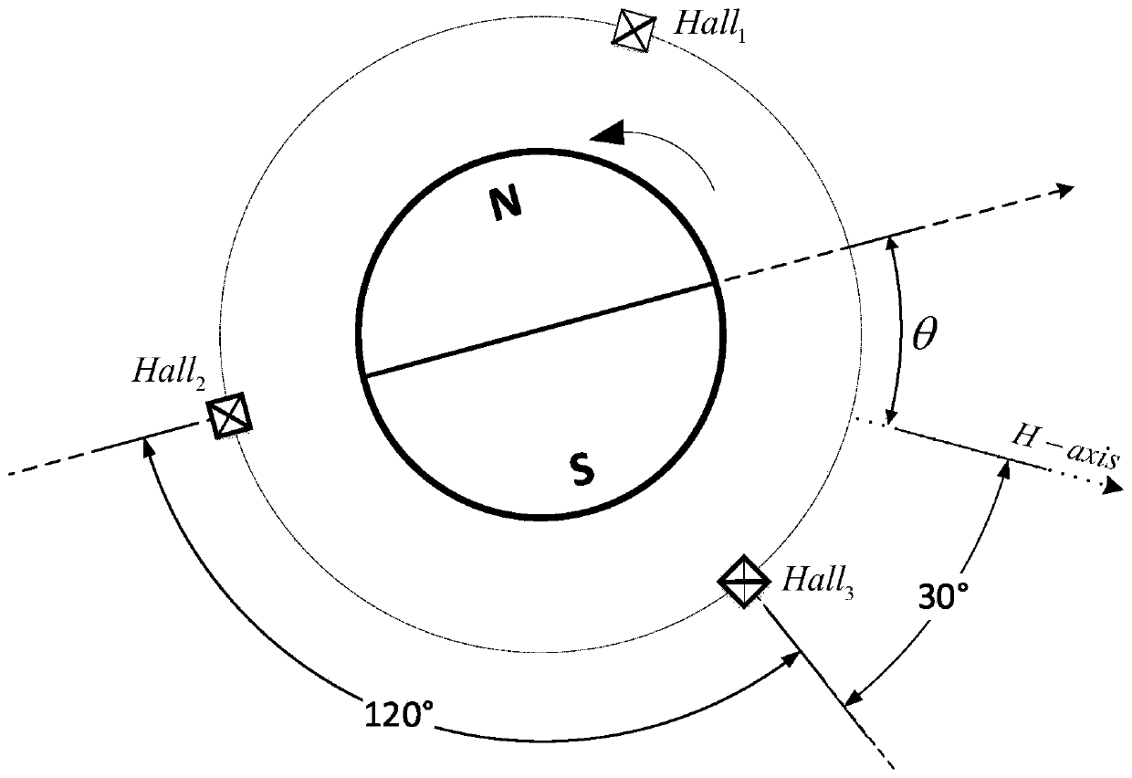
[0022] Such as figure 1 As shown, there are 3 linear Hall sensors evenly arranged around the motor with a difference of 120 degrees. The linear Hall sensor detects the three-phase analog signal as the original static Hall signal:

[0023]

[0024] However, the original static Hall signal has amplitude error and DC error. Among them, θ is the angular displacement of the rotor relative to the Hall sensor, A n and D n (n=1, 2, 3) are respectively the amplitude gain and the DC component of the nth Hall signal, which can be obtained by measurement.

[0025] pass: Convert the three-phase analog ...


PUM


Abstract

The invention discloses a sine driving method of a permanent magnet synchronous motor. According to the invention, three linear Hall sensors uniformly distributed on the periphery of a motor output three-phase analog signals to process the three-phase analog signals to obtain sine waves Hn (n = 1, 2, 3) with a 120-degree fixed phase difference, and then three-phase voltage VN (N = A, B, C) of sine driving is obtained; and a new three-phase voltage is obtained according to a quantitative relation among the angular displacement theta of the rotor relative to the Hall sensors, the angular displacement of the rotor relative to a stator coil and the fixed angle deviation. According to the invention, Hall signal phase shift transformation is realized through a linear combination mode, so that the Hall signals subjected to the phase shift is consistent with an expected voltage vector direction, thereby compensating angular deviation of the sensors and coils under the condition that a trigonometric function is not calculated, and obtaining a three-phase voltage value of sine driving.

Description

technical field [0001] The invention belongs to the technical field of motor drive, and in particular relates to a sinusoidal drive method for a permanent magnet synchronous motor. Background technique [0002] The characteristics of the permanent magnet synchronous motor are suitable for sinusoidal drive, and the calculation of the rotor rotation angle and trigonometric functions is required to obtain the corresponding parameters. The linear Hall sensor has the characteristics of small size and low cost. It not only provides commutation information, but also can replace the high-resolution encoder to realize the position feedback and output the sinusoidal signal of the rotor angle. By linearly combining the Hall signals to obtain the required parameters of the sinusoidal drive, the calculation of trigonometric functions can be avoided, thereby reducing calculation consumption. [0003] The existing paper Position estimation and control of compact bldc motors based on analo...

Claims


Application Information

Patent Timeline
Patent Type & Authority Applications(China)
IPC IPC(8): H02P23/00H02P25/022
CPCH02P23/0004H02P25/022H02P2207/05
Inventor 余张国秦鸣悦陈学超黄强李庆庆张伟民
Owner BEIJING INSTITUTE OF TECHNOLOGYGY
Learn More