
Wind sensor testing device

A technology of a wind sensor and a testing device, which is applied in the field of testing of wind sensors, can solve problems such as lodging, lost people and animals in pastoral areas, blocked roads, etc., and achieves the effect of convenient use.

Pending Publication Date: 2019-09-17
佐格微系统(杭州)有限公司
View PDF0 Cites 3 Cited by
  • Summary
  • Abstract
  • Description
  • Claims
  • Application Information

AI Technical Summary

Problems solved by technology

Strong winds in winter often cause people and animals in pastoral areas to lose their way and freeze to death due to heavy wind and snow and poor visibility. At the same time, blowing snow will block roads, making it difficult to carry out rescue work and aggravate the disaster; strong winds in spring are very destructive. Destruction of houses; typhoons in summer mainly endanger the safety of the city and people, causing tall crops, mature crops, and fruit trees to cause lodging, grain and fruit drop

Method used


Image

  • Wind sensor testing device
  • Wind sensor testing device
  • Wind sensor testing device

Examples


Embodiment 1

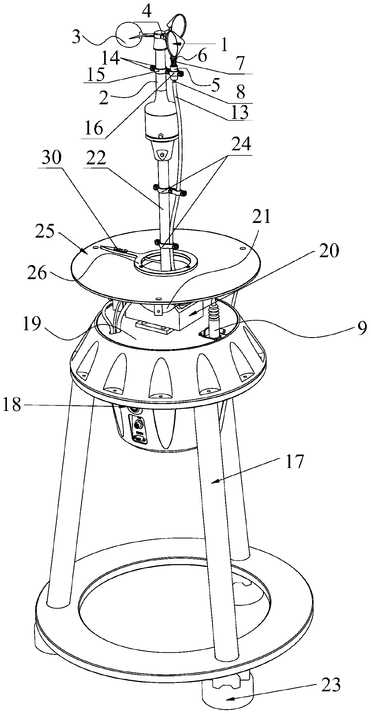
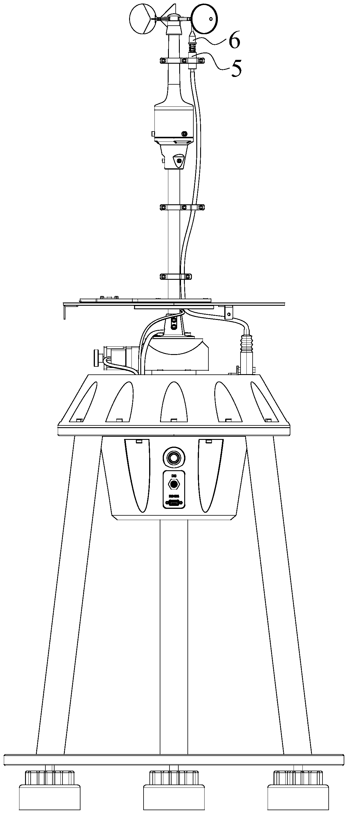
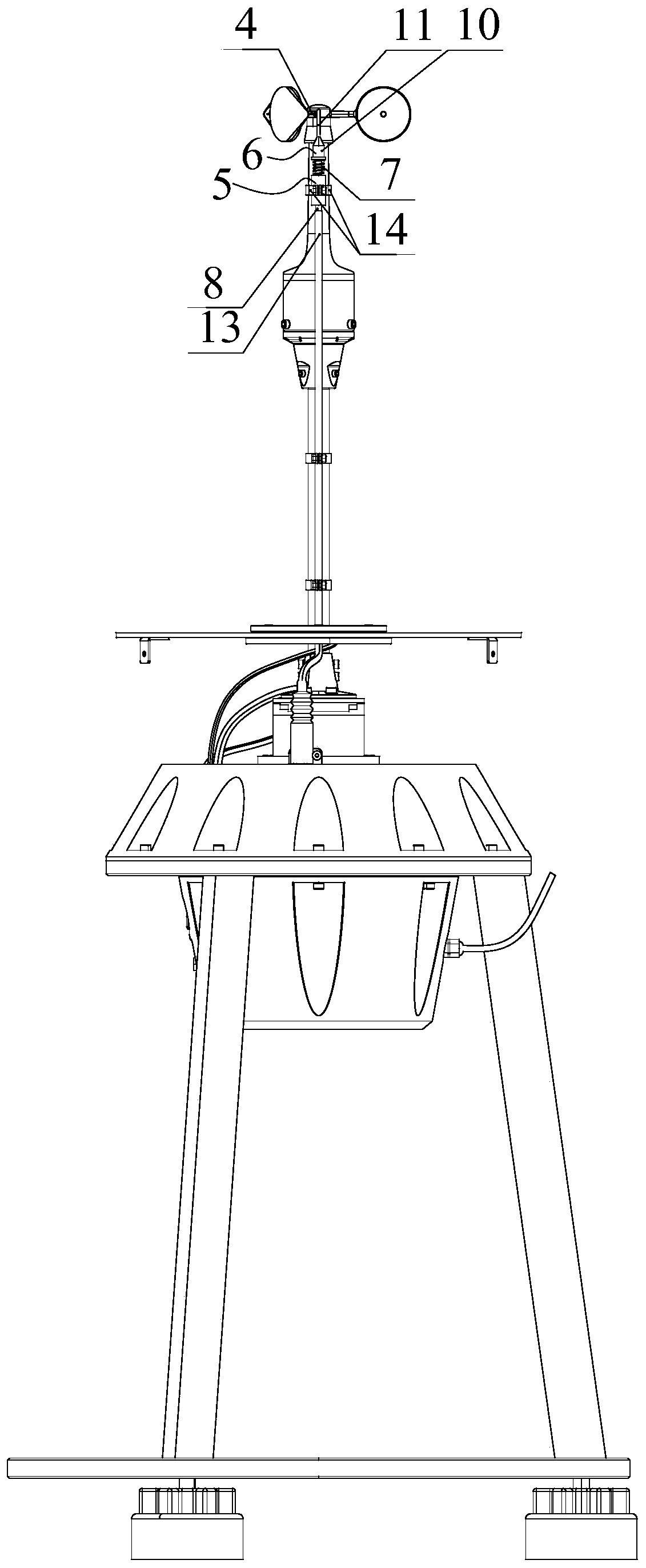
[0044] Such as figure 1 As shown, a wind sensor testing device includes a support rod 22 connected to a fixed base 21 and a fixed base 21, and the support rod 22 is used to install the wind sensor 1, such as figure 1 and 4 As shown, in actual use, the wind sensor 1 can be a wind speed sensor (such as a wind cup) or a wind direction sensor (such as a wind vane).

[0045] Such as figure 1 , 2 As shown in and 3, the wind sensor test device also includes a locking mechanism, and the locking mechanism includes:

[0046] The first mounting seat 5 is used to be fixed on the body 2;

[0047] The locking lever 6 is slidably arranged on the mounting seat. The locking lever 6 has a locking working position and an unlocking working position. When the locking working position is locked, the locking lever 6 moves upwards to cooperate with the rotating part 3 to prevent rotation Part 3 rotates, and when unlocking the working position, the locking lever 6 moves downward and no longer coo...

Embodiment 2

[0074] Such as Figure 6 and 7 As shown, this embodiment discloses a wind sensor testing device. The difference from Embodiment 1 is that it also includes a laser auxiliary mechanism. The laser auxiliary mechanism in this embodiment includes:

[0075] The lower dial 25 is relatively fixed with the support 17, and the circumferential direction of the lower dial 25 has an angle score line (omitted and not shown in the figure);

[0076] Lower pointer 26 is installed on the lower dial 25 in rotation, and the lower pointer 26 is used to point to the angle mark line of the lower dial 25, and the axis of rotation of the lower pointer 26 coincides with the axis of the lower dial 25;

[0077] The upper dial 27 is located above the lower dial 25, and the circumference of the upper dial 27 has an angular scale line (omitted and not shown in the figure), the upper dial 27 and the lower dial 25 are coaxially arranged, and the support rod 22 After the wind sensor 1 is installed, the wind ...


PUM


Abstract

The invention discloses a wind sensor testing device, comprising: a bracket; a horizontal rotating table mounted on the upper part of the bracket, wherein the horizontal rotating table is provided with a rotating seat capable of rotating around a vertical axis; an angle displacement platform mounted on the rotating seat, wherein the angle displacement platform is provided with a fixing seat capable of rotating around a horizontal axis; and a support rod, wherein the lower end of which is fixed to the fixing seat, and a wind sensor is mounted on an upper end of which. The wind sensor is mounted on the upper end of the support rod of the wind sensor testing device, the support rod can be used for adjusting the angle at a horizontal position via the horizontal rotating table and adjusting the angle at a vertical position via the angle displacement platform, therefore the wind sensor testing device disclosed by the invention can adjust the position of the wind sensor at multiple angles, the wind sensor testing device is mounted in a wind tunnel in use, and can test the wind sensor under non-horizontal wind conditions of various angles and various orientations.

Description

technical field [0001] The invention relates to the field of wind sensor testing, in particular to a wind sensor testing device. Background technique [0002] Wind is one of the most important observation elements in meteorological observation. Wind has a major impact on industrial and agricultural production, transportation and people's lives. Strong wind is one of the main disastrous weathers in my country. Strong wind also enhances evaporation, which makes crops suffer from water imbalance and drought. Strong winds in winter often cause people and animals in pastoral areas to lose their way and freeze to death due to heavy wind and snow and poor visibility. At the same time, blowing snow will block roads, making it difficult to carry out rescue work and aggravate the disaster; strong winds in spring are very destructive. Destruction of houses; typhoons in summer mainly endanger the safety of cities and people, causing tall crops, mature crops, and fruit trees to fall, d...

Claims


Application Information

Patent Timeline
Patent Type & Authority Applications(China)
IPC IPC(8): G01P21/02G01P21/00
CPCG01P21/025G01P21/00
Inventor 诸葛杰缪琛彪何杰
Owner 佐格微系统(杭州)有限公司
Learn More