
Camera bracket in three-view microscopic visual auxiliary coupling

A microscopic vision and camera technology, applied in the field of camera brackets, can solve problems such as reducing accuracy, reducing efficiency, and inaccurate accuracy, and achieving the effects of accurate observation, improved performance, and improved accuracy

Inactive Publication Date: 2019-09-17
武汉亿思源光电股份有限公司
View PDF9 Cites 7 Cited by
  • Summary
  • Abstract
  • Description
  • Claims
  • Application Information

AI Technical Summary

Problems solved by technology

[0005] Aiming at the deficiencies of the prior art, the present invention provides a camera bracket for three-view microscopic vision aided coupling, which has the advantages of easy adjustment and convenient use, and solves the problem that the existing camera mounting bracket is not enough in terms of easy adjustment and convenient use. Perfect, which reduces the efficiency of people in use. People need to ensure that the camera can achieve multi-directional observation, and manual adjustments often bring inconvenience to people, resulting in inaccurate observation accuracy and reducing the use of time precision problem

Method used

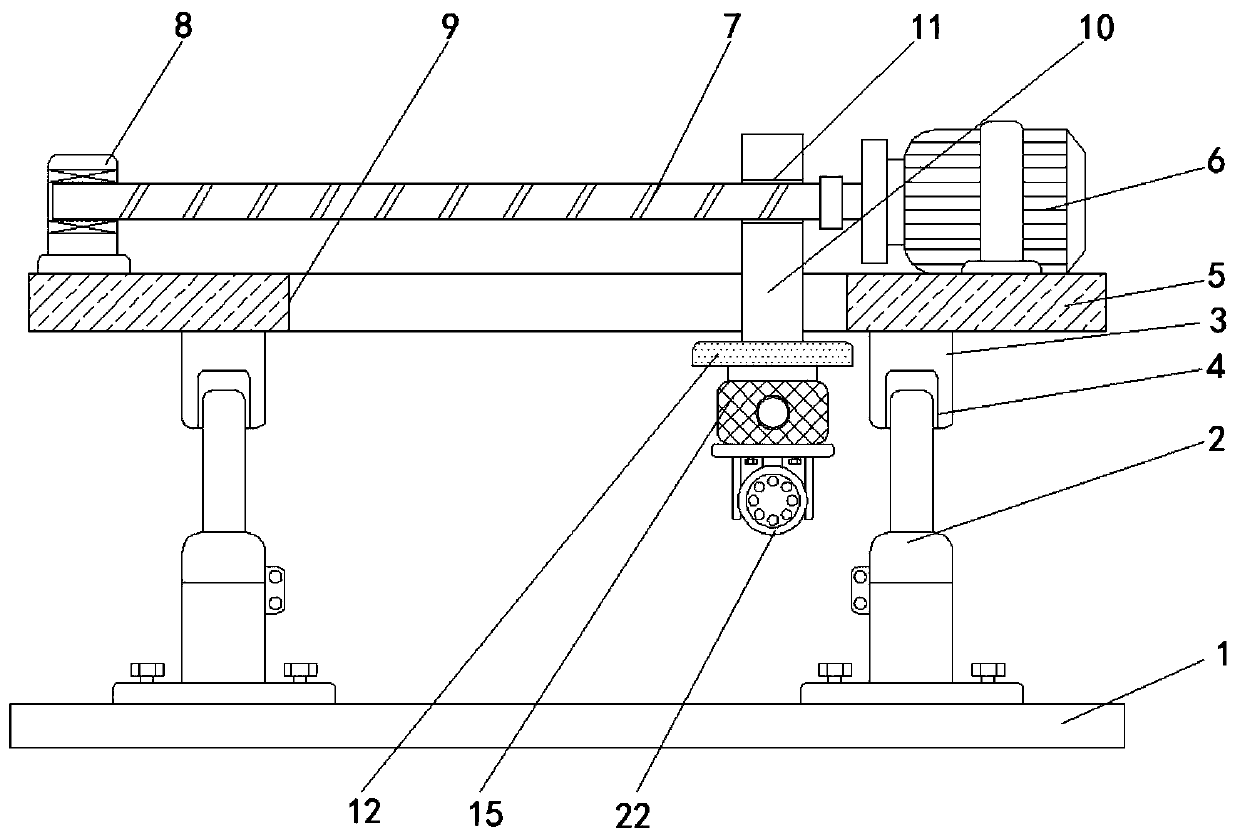

Image

  • Camera bracket in three-view microscopic visual auxiliary coupling
  • Camera bracket in three-view microscopic visual auxiliary coupling

Examples


Embodiment Construction

[0023] The following will clearly and completely describe the technical solutions in the embodiments of the present invention with reference to the accompanying drawings in the embodiments of the present invention. Obviously, the described embodiments are only some, not all, embodiments of the present invention. Based on the embodiments of the present invention, all other embodiments obtained by persons of ordinary skill in the art without making creative efforts belong to the protection scope of the present invention.

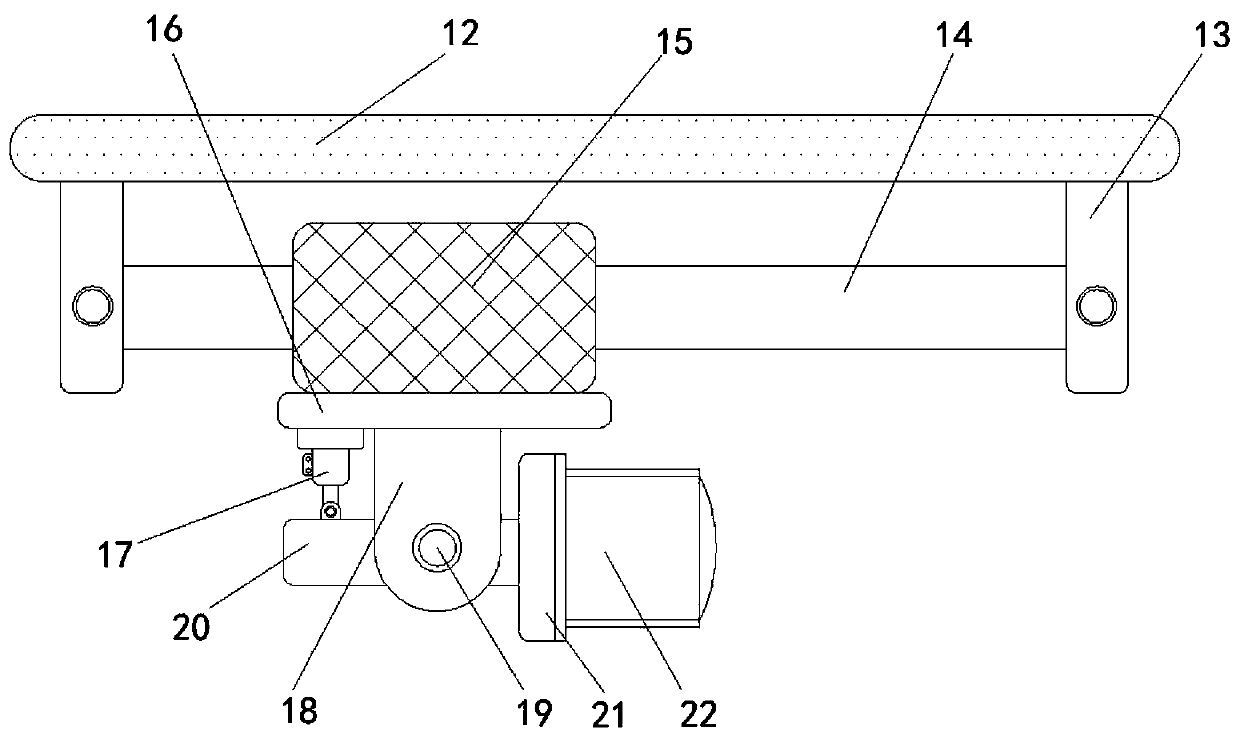
[0024] see Figure 1-2, the camera bracket in the three-view microscopic vision aided coupling, including a stable base plate 1, an electric push rod 2, a connecting groove 3, a connecting block 4, a mounting substrate 5, a driving motor 6, a screw rod 7, a fixed block 8, and a chute 9 , sliding block 10, threaded hole 11, mounting plate 12, matching block 13, conduction tube 14, sliding block 15, fixing plate 16, electric telescopic rod 17, positioning block ...


PUM


Abstract

The invention relates to the technical field of camera brackets, and discloses a camera bracket in three-vision micro-vision auxiliary coupling. The camera bracket comprises a stable bottom plate, electric push rods, a connecting groove, a connecting block, a mounting base plate, a driving motor, a screw rod, a fixing block, a sliding chute, a movable block, a threaded hole, a mounting plate, a matching block, a conduction pipe, a sliding block, a fixing plate, an electric telescopic rod, a positioning block, a rotating shaft, a stabilizing plate, a round block and a camera body, wherein two electric push rods are fixedly mounted at the top of the stable bottom plate, and the connecting block is fixedly arranged at the bottom of the mounting base plate. The camera bracket in the three-view microscopic visual auxiliary coupling can ensure that the camera can observe an object; meanwhile, the conduction pipe is arranged at the bottom of the mounting plate, the sliding block performs magnetic coupling sliding on the conduction pipe, so that the movement in the front-back direction of the camera can be better achieved, thus ensuring that the object can be observed in multiple directions when the camera is used so as to improve the performance of the camera during observation.

Description

technical field [0001] The invention relates to the technical field of camera brackets, in particular to a camera bracket for three-view microscopic vision aided coupling. Background technique [0002] The camera generally has basic functions such as video recording, transmission and static image capture. After collecting images through the lens, the photosensitive component circuit and control components in the camera process the image and convert it into a digital signal that can be recognized by the computer. After inputting to the computer through the parallel port or USB connection, the software will restore the image. When using the camera, a bracket is often used. [0003] For example, the height-adjustable camera mounting bracket disclosed in Chinese patent CN 105485489 B includes a base, a block is provided at the bottom of the base, a platform is provided above the base, and a height adjustment device is provided on both sides of the base, and the height adjustment...

Claims


Application Information

Patent Timeline
Patent Type & Authority Applications(China)
IPC IPC(8): F16M11/04F16M11/10F16M11/18F16M11/24H04N5/225
CPCF16M11/18F16M11/24F16M11/10F16M11/045H04N23/00
Inventor 荣彬彬
Owner 武汉亿思源光电股份有限公司
Learn More