
A pipe shed installation device for underground engineering tunnels

An installation device and technology for underground engineering, applied in tunnels, tunnel linings, underground chambers, etc., can solve problems such as low installation efficiency, inability to connect conduits, thread deformation, etc., to improve moving efficiency and reduce the number of manual thread supplements , the effect of increasing the contact area

Active Publication Date: 2020-11-03
LIAONING TECHNICAL UNIVERSITY
View PDF6 Cites 0 Cited by
  • Summary
  • Abstract
  • Description
  • Claims
  • Application Information

AI Technical Summary

Problems solved by technology

[0003] However, most of the existing pipe shed installations rely on a mechanical device at the rear end to push the conduit into the rotating hole, which makes it easy to deform the threads of the threaded fasteners on the conduit so that it cannot be connected after the conduit is inserted. At the same time, the existing conduit Most of the threaded fasteners on the pipe are installed manually, and the installation efficiency is low. At the same time, when the pipe shed is installed at a higher place, workers are prone to accidents when working at a high place.

Method used


Image

  • A pipe shed installation device for underground engineering tunnels
  • A pipe shed installation device for underground engineering tunnels
  • A pipe shed installation device for underground engineering tunnels

Examples


Embodiment Construction

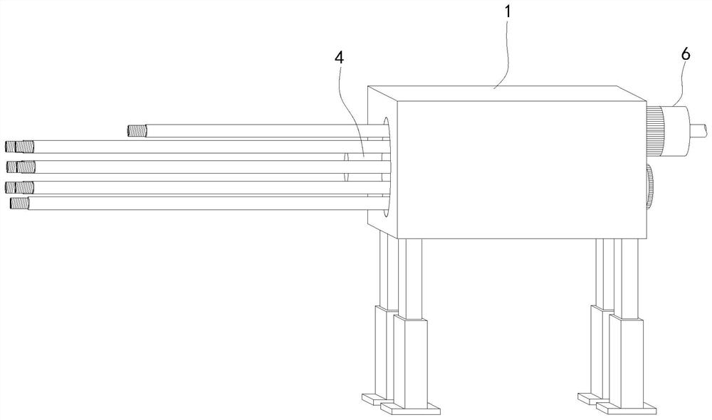
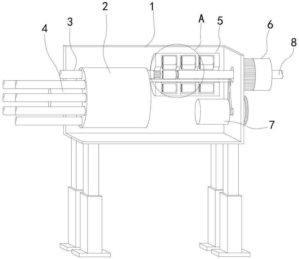
[0028] see Figures 1 to 10 , a planar structure schematic diagram and a three-dimensional structural schematic diagram of a tube shed installation device for an underground engineering tunnel.

[0029] A pipe shed installation device for underground engineering tunnels, including a device main body, characterized in that: a pipe transfer device is fixedly installed inside the device main body, a screw thread installation device is fixedly installed on the right end of the device main body, and a propulsion device.

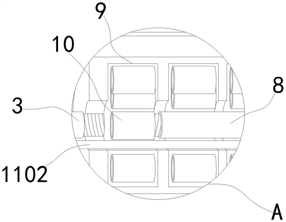
[0030] In a specific implementation, a rotating layer is movably installed inside the tube transfer device, a catheter lumen is opened on the rotating layer and the bottom end of the catheter lumen is open, and a second catheter is movably installed in the catheter lumen, so that when the first motor 4 Drive the rotating propulsion rod 11 to rotate so that it can drive the second catheter 3 to move to the right through the bottom end of the catheter lumen 12 to c...


PUM


Abstract

The invention relates to the field of tunnel construction, in particular to a pipe shed mounting device for an underground engineering tunnel. A pipe rotating device is fixedly mounted in a device body, a screw thread mounting device is fixedly mounted on the right end side of the pipe rotating device, and a propelling device is fixedly mounted on the right side of the exterior of the device body. Rotating columns are arranged in a rotationally forward mode and mounted at the upper end and the lower end of the propelling device, thus the rotating columns can provide forward force for a first guiding pipe, the rotating force of the rotating columns at the upper end and the lower end is counteracted while thread deformation caused by force bearing of the two ends of the guiding pipe is avoided, accordingly, it is ensured that the first guiding pipe can travel straight, the situation that fixed screw threads are loosened due to rotation is avoided, then through arrangement of hexagons of the front ends of through holes in the rotating columns, when the rotating columns make contact with the first guiding pipe to extrude an internal rubber layer, the rubber layer is diffused outwards to enable the contact area of the rubber layer and the first guiding pipe to be increased, and thus the rotating columns drive the first guiding pipe to move more efficiently.

Description

technical field [0001] The invention relates to the field of tunnel construction, in particular to a pipe shed installation device for underground engineering tunnels. Background technique [0002] The pipe shed is mainly used as an advanced support structure in the weak and broken surrounding rock tunnel engineering with strict restrictions on surrounding rock deformation and surface subsidence. The pipe shed constructed in advance provides a fulcrum for the front surrounding rock support and the rear surrounding rock. A beam structure is formed, and the two form a shell-like structure surrounding the tunnel contour, which can effectively restrain the surrounding rock from loosening and collapsing. [0003] However, most of the existing pipe shed installations rely on a mechanical device at the rear end to push the conduit into the rotating hole, which makes it easy to deform the threads of the threaded fasteners on the conduit so that it cannot be connected after the condu...

Claims


Application Information

Patent Timeline
Patent Type & Authority Patents(China)
IPC IPC(8): E21D11/10E21D11/14
CPCE21D11/006E21D11/10E21D11/14
Inventor 宋洋祝百茹王亚星
Owner LIAONING TECHNICAL UNIVERSITY
Learn More