Ejector rod rapid modeling method for die-casting mold

A modeling method and die-casting mold technology, applied in special data processing applications, instruments, electrical and digital data processing, etc., can solve problems such as difficult positioning of the ejector, difficult measurement, and error-prone, to ensure accuracy and reduce repairs. Cost and effect of shortening R&D cycle

Inactive Publication Date: 2019-09-13
ZHEJIANG WANXIANG SYST +1
View PDF0 Cites 0 Cited by
  • Summary
  • Abstract
  • Description
  • Claims
  • Application Information

AI Technical Summary

Problems solved by technology

refer to figure 2 , the core model is the most complex in the whole set of molds, with thousands or tens of thousands of geometric surfaces, so it is extremely difficult to locate the exit position of the ejector pin on the core, making measurement extremely difficult and error-prone

Method used


Image

  • Ejector rod rapid modeling method for die-casting mold
  • Ejector rod rapid modeling method for die-casting mold
  • Ejector rod rapid modeling method for die-casting mold

Examples


Embodiment

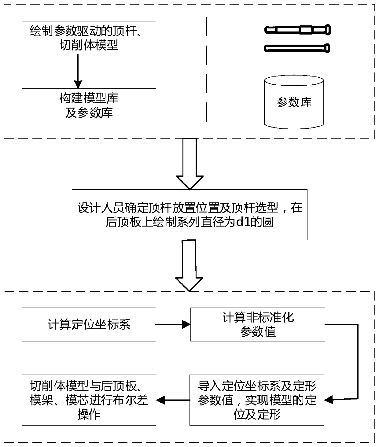
[0067] 1. Draw the three-dimensional model of ejector pin and cutting body driven by parameters

[0068] refer to Figure 5 , first draw the three-dimensional model of the ejector rod according to the position of the positioning coordinate system, and define the ejector rod parameter variable d 1 、d 2 、h 1 、h 2 , and establish the driving relationship between the parameter variables and the three-dimensional model, and complete the establishment of the parametric driven ejector model.

[0069] The three-dimensional model of the cutting body is consistent with the positioning coordinate system of the three-dimensional model of the ejector rod, and the parameter variable D of the cutting body is defined 1 、D 2 、D D 、D 5 、H 1 、H 2 、H 3 、H 4 、H 5 , establish the driving relationship between the parameter variable and the three-dimensional model, and complete the establishment of the parameterized driving cutting body model.

[0070] 2. Establish a standardized paramet...


PUM


Abstract

The invention discloses an ejector rod rapid modeling method for a die-casting mold. The ejector rod rapid modeling method comprises the following steps: constructing a parameterized driven ejector rod and cutting body model, and dividing the parameterized driven ejector rod and cutting body model into standard parameters and non-standard parameters by analyzing parameter types, wherein the standardized parameters are assigned by directly reading the parameters in a database, and the non-standardized parameters establish a relationship with a rear top plate, a mold frame and a mold core model,and the non-standardized parameters are deduced reversely by automatically calculating the distances among the rear top plate, the mold frame and the mold core; and calculating a positioning coordinate system of the ejector rod and the cutting body. The ejector rod rapid modeling method has the beneficial effects that when the ejector rod rapid modeling method is adopted, the modeling workload ofmold designers is greatly reduced. By adopting the ejector rod rapid modeling method provided by the invention, the accuracy of the ejector rod and the cutting body model is ensured, and the checkingwork on the model accuracy is directly omitted, and only the placement point of the ejector rod and the type selection are required to be checked accurately, so that the research and development period of the mold is further shortened, and the mold repair cost caused by inaccurate model is reduced.

Description

technical field [0001] The invention relates to the field of die-casting molds, and mainly relates to a rapid modeling method for ejector pins of die-casting molds. Background technique [0002] Die-casting mold is an indispensable link in the mass production process. In the die-casting mold, the ejector pin is mainly used to separate the die-casting product from the punch or die from the punch or die. refer to figure 1 , a medium-sized mold, about 100 ejector pins need to be designed. After the mold designer completes the parameter selection and positioning of the ejector pin, he needs to draw a three-dimensional model of the ejector pin. However, in the drawing process, not only the three-dimensional model of the ejector pin needs to be drawn, but also the cutting body model of the ejector pin 3 needs to be drawn, and the Boolean difference operation with the rear top plate 2, mold base 1, and mold core 4 is performed to generate an air-avoiding area. Different types of...

Claims


Application Information

Patent Timeline
Patent Type & Authority Applications(China)
IPC IPC(8): G06F17/50
CPCG06F30/17G06F30/20
Inventor 邵立张永祥罗美玲肖义珏
Owner ZHEJIANG WANXIANG SYST
Why Eureka
Try Eureka