
Bearing centrifugal testbed

A centrifugal test and bearing technology, which is used in mechanical bearing testing, mechanical component testing, and machine/structural component testing, etc. It can solve the problem that the operation is not convenient enough to use, the testing and testing equipment cannot provide good vibration effects, and the structure of the test bench complex issues

Pending Publication Date: 2019-09-10
C&U CO LTD +2
View PDF7 Cites 2 Cited by
  • Summary
  • Abstract
  • Description
  • Claims
  • Application Information

AI Technical Summary

Problems solved by technology

However, in some actual working conditions, such as compactors or flywheels, the outer ring of the bearing is subjected to rotational loads, and the existing test benches cannot simulate similar working conditions. To provide a certain vibration effect for testing bearings, the existing testing equipment cannot provide a good vibration effect. At the same time, the existing test bench has a complex structure and is not easy to operate and use.

Method used


Image

  • Bearing centrifugal testbed
  • Bearing centrifugal testbed
  • Bearing centrifugal testbed

Examples


Embodiment Construction

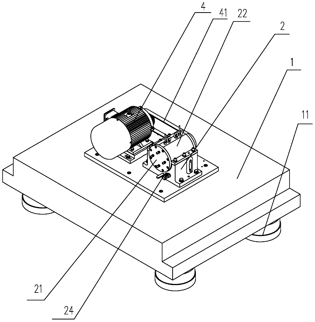
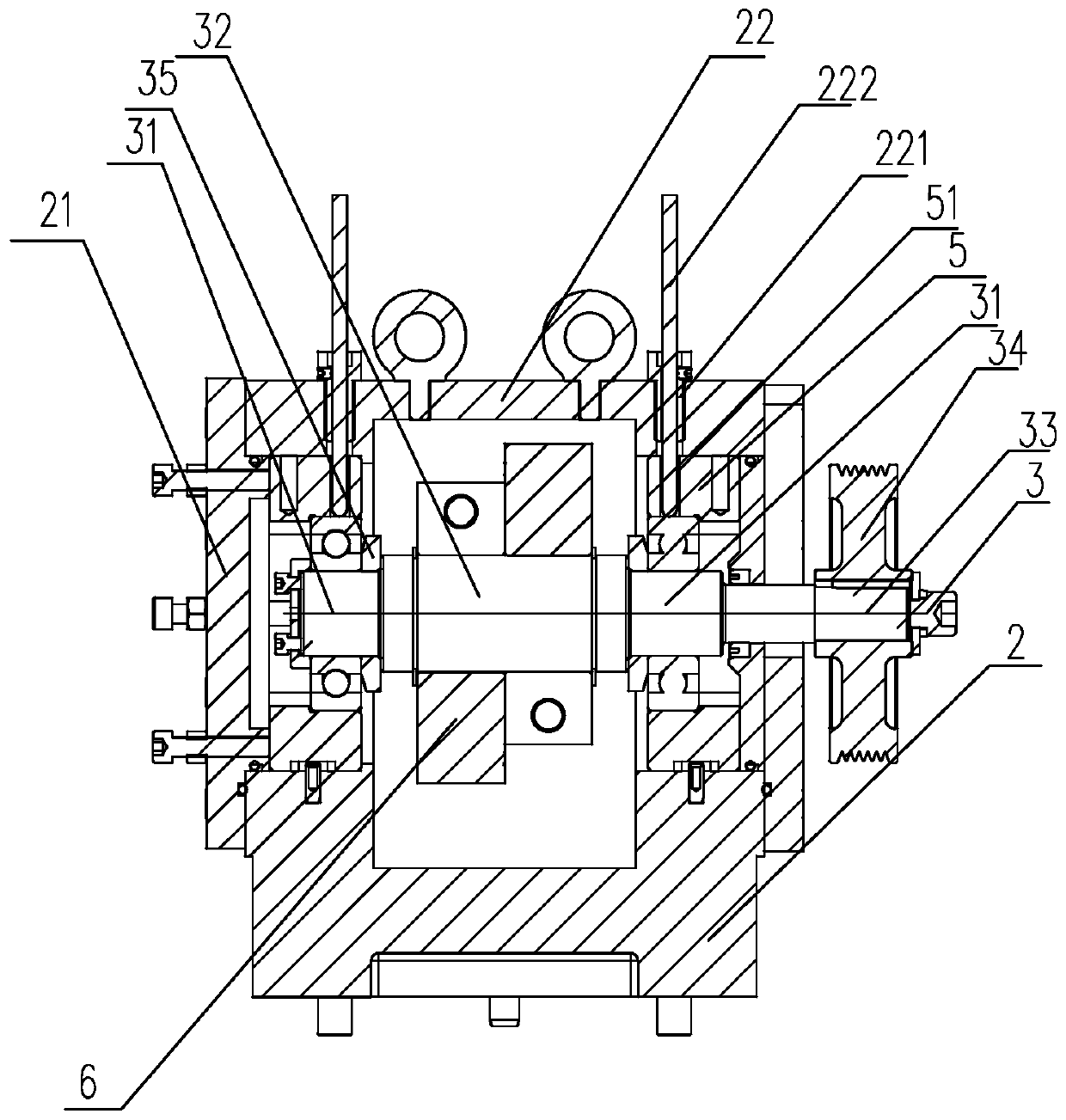
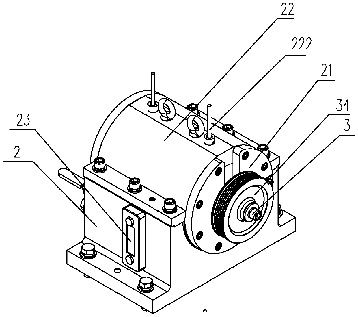
[0023] Depend on Figure 1 to Figure 5 It can be seen that a bearing centrifugal test bench is disclosed, including a bearing seat 1, a drive motor 4 and a test bench 2 for installing the bearing to be tested, the test bench 2 is set on the bearing seat 1, and the drive motor 4 is set On the bearing and arranged on one side of the test bench 2, a mounting groove is formed on the test bench 2, and a mandrel 3 is arranged in the mounting groove, and the mandrel 3 is installed in the mounting groove through a bushing 5, The bush 5 is provided with a positioning groove for installing the bearing to be tested. The mandrel 3 includes a test part 31, a counterweight part 32 and a transmission part 33. The test part 31 is arranged at the corresponding position of the bush 5, so The test part 31 is provided with a backing plate 35 for positioning the bearing to be tested, and the combination of the positioning groove and the backing plate 35 forms the locking of the bearing to be teste...


PUM


Abstract

The invention discloses a bearing centrifugal testbed. The bearing centrifugal testbed comprises a bearing seat, a driving motor, and a testing table for mounting a to-be-tested bearing; the testing table is arranged on the bearing seat, a mounting slot is formed on the testing table, a spindle is arranged in the mounting slot, the spindle is arranged in the mounting slot through a bush, and a positioning slot is arranged on the bush; the spindle comprises a testing part, a balance weight part and a transmission part; the testing part is arranged at a bush corresponding location, a base plateis arranged on the testing part, the positioning slot and the base plate are combined to form the locking on a to-be-tested bearing; the transmission part is arranged at the external of the testing table, a belt pulley is sleeved on the transmission part, the belt pulley is connected with a driving part output end through a belt to form the driving on the rotation of the spindle by the driving motor; the balance weight part is arranged in the mounting slot, and an eccentric block is arranged on the balance weight part. The testbed disclosed by the invention is simple in structure, capable of testing the capacity for bearing the rotating load by the outer ring of the bearing, and the testbed can provide a certain vibration effect, and the testing is closer to the working environment.

Description

technical field [0001] The invention relates to the technical field of bearing testing equipment, in particular to a bearing centrifugal rotation test bench. Background technique [0002] The bearing is the "joint" of the machine, and the bearing has a vital influence on the performance of the equipment. Rolling bearings are usually used with the outer ring fixed and the inner ring rotating. However, in some actual working conditions, such as compactors or flywheels, the outer ring of the bearing is subjected to rotational loads, and the existing test benches cannot simulate similar working conditions. To provide a certain vibration effect for testing bearings, the existing testing equipment cannot provide a good vibration effect. At the same time, the existing test bench has a complex structure and is not convenient enough to operate. Contents of the invention [0003] Aiming at the deficiencies of the prior art, the present invention provides a bearing centrifugal test...

Claims


Application Information

Patent Timeline
IPC IPC(8): G01M13/04G01M13/045
CPCG01M13/04G01M13/045
Inventor 王超
Owner C&U CO LTD
Learn More