
Camera module debugging method, camera module and storage medium

A technology of camera module and debugging method, which is applied in image communication, television, electrical components, etc., and can solve problems affecting the focusing accuracy and speed of the camera module, reducing the performance of the camera module, etc.

Active Publication Date: 2019-09-06
GUANGDONG OPPO MOBILE TELECOMM CORP LTD
View PDF7 Cites 6 Cited by
  • Summary
  • Abstract
  • Description
  • Claims
  • Application Information

AI Technical Summary

Problems solved by technology

[0003] However, after being installed in the terminal, due to the influence of other modules around, the performance information of the OTP programming of the camera module when it leaves the factory may also be affected and changed, thereby affecting the focusing accuracy and speed of the camera module and reducing the performance of the camera module. performance

Method used


Image

  • Camera module debugging method, camera module and storage medium
  • Camera module debugging method, camera module and storage medium
  • Camera module debugging method, camera module and storage medium

Examples


Embodiment Construction

[0043] The technical solutions in the embodiments of the present application will be clearly and completely described below in conjunction with the drawings in the embodiments of the present application. It should be understood that the specific embodiments described here are only used to explain the related application, not to limit the application. It should also be noted that, for the convenience of description, only the parts related to the relevant application are shown in the drawings.

[0044] With the rapid development of terminal technology, users have higher and higher requirements on the imaging effect of the camera module in the terminal. However, due to individual differences, each camera module has different imaging effects, and it is difficult to achieve consistent imaging effects for all cameras with only a set of fixed imaging parameters. In order to overcome the difference in performance between different camera modules and ensure the consistency of the came...


PUM


Abstract

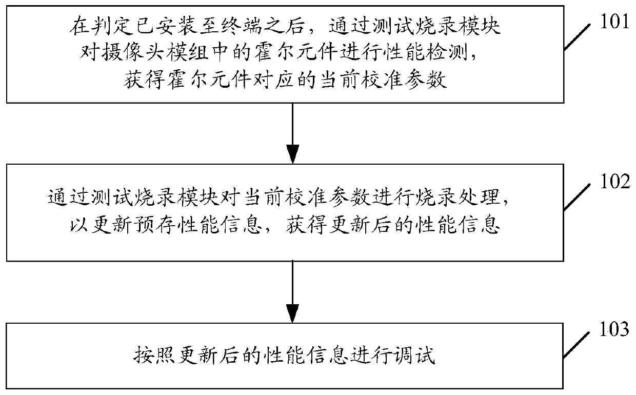
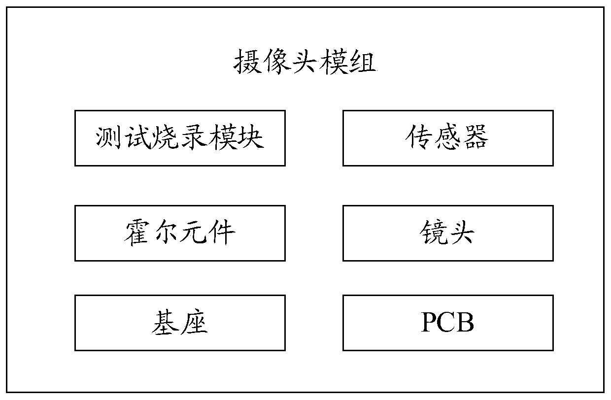
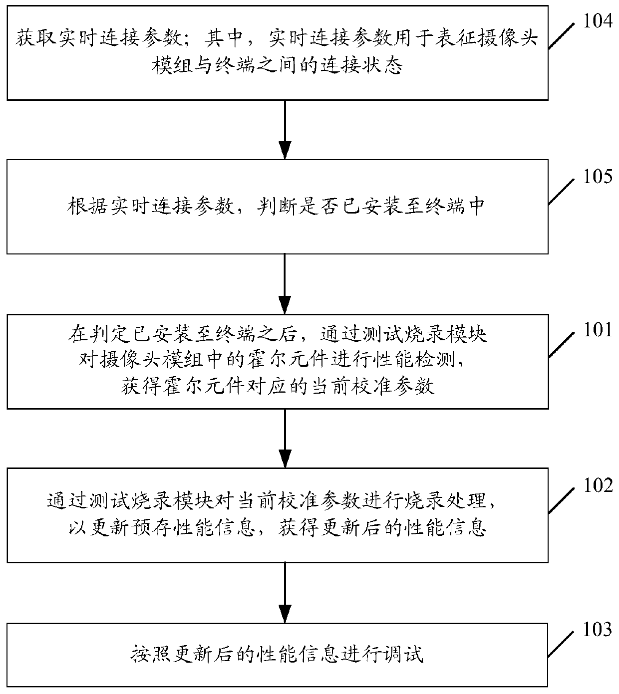
The embodiment of the invention discloses a camera module debugging method, a camera module and a storage medium. The debugging method of the camera module is applied to the camera module, the cameramodule comprises a test burning module, and the debugging method of the camera module comprises the steps that after it is judged that the camera module is installed on a terminal, performance detection is conducted on Hall elements in the camera module through the test burning module, and current calibration parameters corresponding to the Hall elements are obtained; the current calibration parameters are burned through a test burning module so as to update pre-stored performance information and obtain updated performance information; and debugging is carried out according to the updated performance information.

Description

technical field [0001] The embodiments of the present application relate to the technical field of camera modules, and in particular, to a method for debugging a camera module, a camera module, and a storage medium. Background technique [0002] With the rapid development of cameras, users have higher and higher requirements on the imaging effects of cameras. In order to improve the imaging effect of the camera, before leaving the factory, the camera module is generally tested and burned for one-time storage data (One timeprogram, OTP). Specifically, the camera module can quickly improve the speed and accuracy of autofocus by burning performance information. [0003] However, after being installed in the terminal, due to the influence of other modules around, the performance information burned by OTP when the camera module leaves the factory may also be affected and changed, thereby affecting the focusing accuracy and speed of the camera module and reducing the performance ...

Claims


Application Information

Patent Timeline
Patent Type & Authority Applications(China)
IPC IPC(8): H04N17/00
CPCH04N17/002
Inventor 林俊国
Owner GUANGDONG OPPO MOBILE TELECOMM CORP LTD
Learn More