
Steel structure equipment for municipal bridge construction

A bridge construction and equipment technology, applied in bridge construction, bridges, erection/assembly of bridges, etc., can solve problems such as reduced work efficiency, increased equipment cost, material failure, etc., to improve construction efficiency, prevent water and liquid accumulation, and improve practicality. sexual effect

Inactive Publication Date: 2019-09-06
黄益艺
View PDF12 Cites 4 Cited by
  • Summary
  • Abstract
  • Description
  • Claims
  • Application Information

AI Technical Summary

Problems solved by technology

[0002] The steel structure has the characteristics of easy installation and is widely used in all walks of life. During municipal construction, bridges are often erected on small rivers to facilitate the passage of pedestrians and vehicles. During construction, construction workers often use wood to build construction platforms. , so as to facilitate the construction operations of construction personnel, but this increases the labor burden of bridge erection on the water surface to a large extent and increases the cost of equipment, which reduces the work efficiency of people when building. The volume of erecting equipment is large, which is very inconvenient in the process of transportation and installation, making it difficult to promote in large quantities, and because of different depths of water, the height of the equipment needs to be changed to fully offset and fix the bottom of the water. Traditional equipment The method is to pre-process materials of different heights and then install them uniformly. This makes the materials invalid if the depth of the installation site changes, and it is necessary to remanufacture and transport materials of different heights to the site for installation. This makes the equipment extremely inconvenient to work, and the above shortcomings largely hinder the efficient use of personnel to build water surface steel structure equipment

Method used


Image

  • Steel structure equipment for municipal bridge construction
  • Steel structure equipment for municipal bridge construction
  • Steel structure equipment for municipal bridge construction

Examples


Embodiment Construction

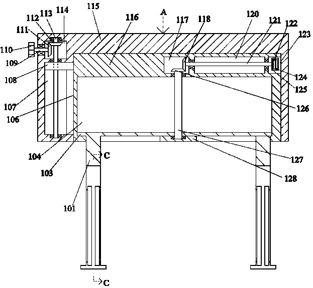
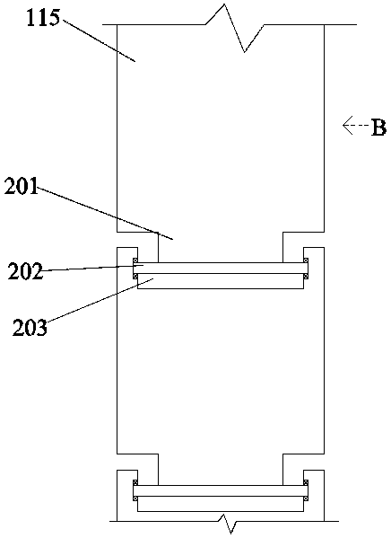
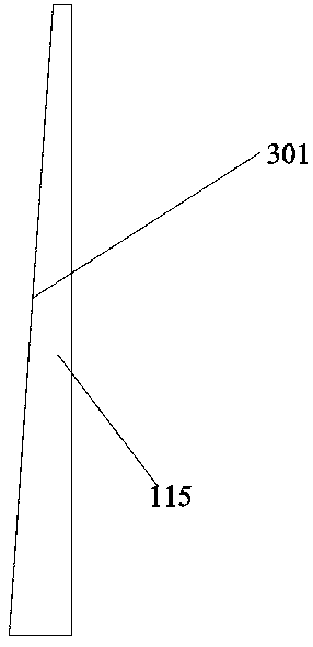
[0023] Such as Figure 1-Figure 4 As shown, the present invention is described in detail. For the convenience of description, the orientations mentioned below are now stipulated as follows: figure 1 The up, down, left, right, front and back directions of the projection relationship are consistent. A steel structure equipment for municipal bridge construction of the present invention includes a plurality of boxes 115, and the box 115 is provided with a cavity 106 with an opening facing downward. The left end wall of 106 is communicated with a side cavity 107, and above the side cavity 107 is an upper cavity 114 located in the box body 115. The cavity 106 is provided with a supporting device for unfolding and efficiently supporting the equipment. The left side of the supporting device is provided with a driving device located in the side cavity 107 and the upper side cavity 114 to adjust the extension of the supporting device, and the box bodies 115 are connected through a conne...


PUM


Abstract

The invention discloses steel structure equipment for municipal bridge construction. The steel structure equipment comprises a plurality of box bodies. Accommodation cavities with downward openings are arranged inside the box bodies; side cavities are arranged in the left end walls of the accommodation cavities in a communicating manner; upper side cavities positioned inside the box bodies are arranged above the side cavities; supporting devices for being unfolded to enable the equipment to perform efficient supporting are arranged inside the accommodation cavities; the left sides of the supporting devices are provided with driving devices; the driving devices are positioned inside the side cavities and the upper side cavities and used for adjusting the supporting devices to extend; and the box bodies are cooperatively connected by connection devices. The steel structure equipment is simple in structure; the steel structure equipment adopts the design of the supporting devices, the driving devices and the connection devices, and realizes the function of facilitating the folding and installation by people; the steel structure equipment can be quickly adjusted and installed for different heights in the case of multiple-group arrangement; and the steel structure equipment has good stability so as to improve the practicality of the equipment.

Description

technical field [0001] The invention relates to the technical field of municipal bridge construction, in particular to steel structure equipment for municipal bridge construction. Background technique [0002] The steel structure has the characteristics of easy installation and is widely used in all walks of life. During municipal construction, bridges are often erected on small rivers to facilitate the passage of pedestrians and vehicles. During construction, construction workers often use wood to build construction platforms. , so as to facilitate the construction operations of construction personnel, but this increases the labor burden of bridge erection on the water surface to a large extent and increases the cost of equipment, which reduces the work efficiency of people when building. The volume of erecting equipment is large, which is very inconvenient in the process of transportation and installation, making it difficult to promote in large quantities, and because of ...

Claims


Application Information

Patent Timeline
IPC IPC(8): E01D21/00
CPCE01D21/00
Inventor 不公告发明人
Owner 黄益艺
Learn More