
Electro-optic phase modulator with low residual amplitude modulation

An electro-optical phase modulation and amplitude modulation technology, which is applied in the fields of instruments, optics, nonlinear optics, etc., can solve the problems of increasing the difficulty of optical path adjustment and arrangement, high precision requirements for electro-optic crystal placement, unfavorable device miniaturization, etc., to achieve effective Conducive to miniaturization, low alignment conditions, and large effective length

Pending Publication Date: 2019-08-30
XI'AN INST OF OPTICS & FINE MECHANICS - CHINESE ACAD OF SCI
View PDF0 Cites 3 Cited by
  • Summary
  • Abstract
  • Description
  • Claims
  • Application Information

AI Technical Summary

Problems solved by technology

[0006] In order to solve the existing solutions for reducing residual amplitude modulation, the effect of residual amplitude modulation can only be weakened to a certain extent, and the operation is cumbersome and time-consuming, which increases the difficulty of optical path adjustment and layout, and requires high precision for the placement of electro-optic crystals, which is not conducive to devices. To solve the technical problem of miniaturization, the present invention provides an electro-optic phase modulator with low residual amplitude modulation

Method used


Image

  • Electro-optic phase modulator with low residual amplitude modulation
  • Electro-optic phase modulator with low residual amplitude modulation
  • Electro-optic phase modulator with low residual amplitude modulation

Examples


Embodiment Construction

[0042] The present invention will be described in detail below in conjunction with the accompanying drawings.

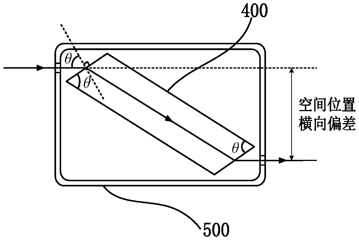
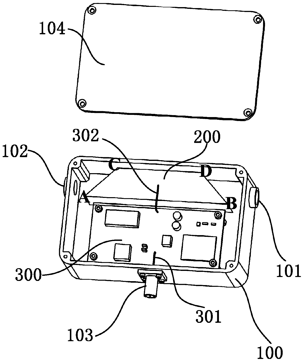
[0043] Such as figure 2 As shown, the electro-optic phase modulator with low residual amplitude modulation provided by the present invention includes an electro-optic crystal 200, a housing 100, and a radio frequency circuit 300;

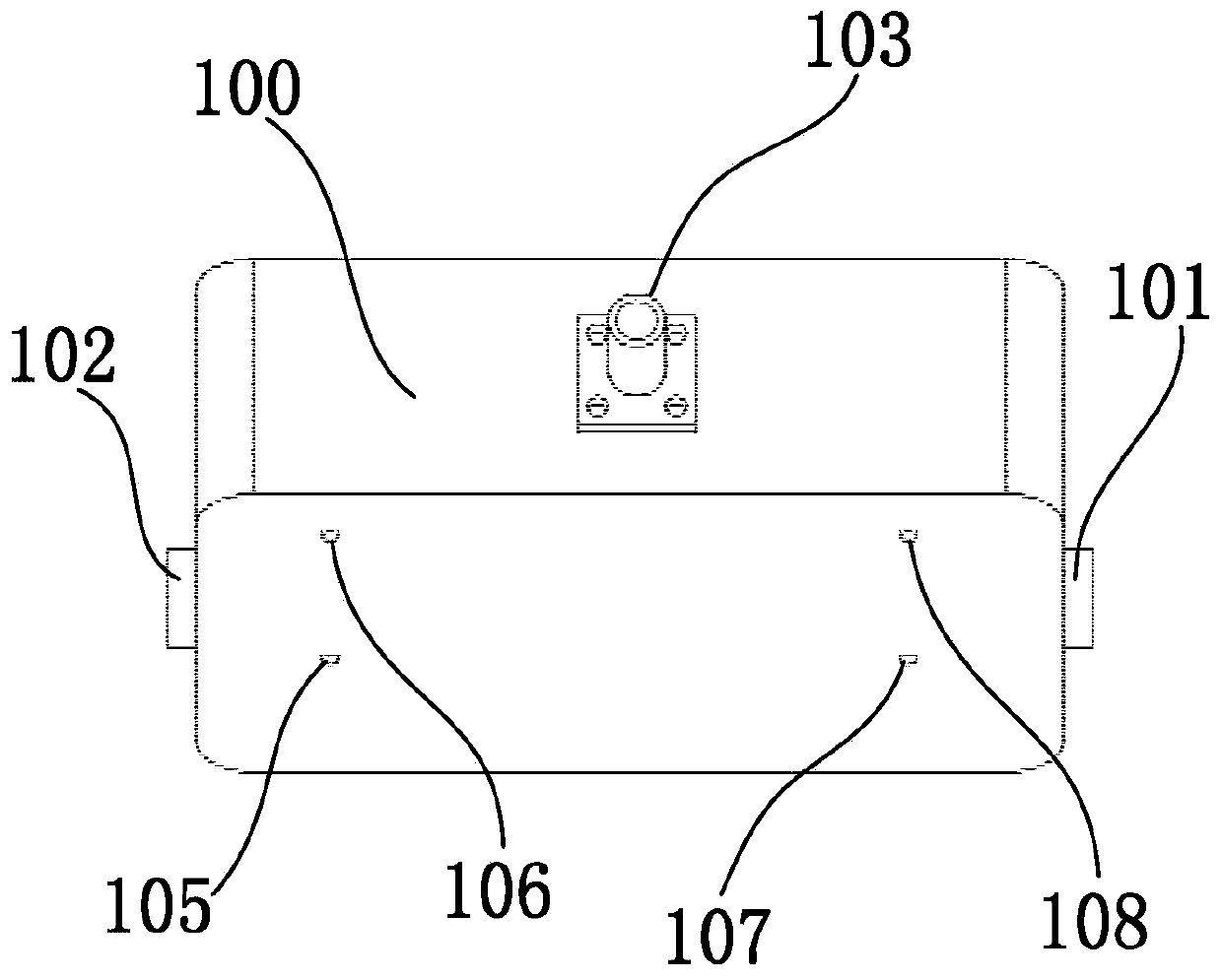
[0044] The housing 100 is a hollow cuboid with a closed bottom and an open top, and the top is closed by a cover plate 104 . The housing 100 is made of copper;

[0045] Such as Figure 4As shown, the electro-optic crystal 200 includes an upper electrode surface ABCD, a lower electrode surface A'B'C'D', a first light-transmitting surface ACA'C', a second light-transmitting surface DBD'B', a first light-reflecting surface ABA' B' and the second reflective surface CDC'D';

[0046] The upper electrode surface ABCD and the lower electrode surface A'B'C'D' are congruent trapezoids, and the two are parallel to each other, and the distance bet...


PUM

PropertyMeasurementUnit
surface roughnessaaaaaaaaaa
electro-optic coefficientaaaaaaaaaa
reflectanceaaaaaaaaaa

Abstract

The invention provides an electro-optic phase modulator with low residual amplitude modulation for solving the technical problems that in the existing scheme of reducing the residual amplitude modulation, the residual amplitude modulation effect can only be weakened to a certain extent, the operation is tedious and time-consuming, the difficulty of optical path adjustment and arrangement is increased, the requirement for placement precision of electro-optic crystals is high, and miniaturization of devices is not facilitated. An electro-optic crystal with a special structure is designed, and the light-passing surface of the electro-optic crystal corresponds to a light-passing hole in a shell in position, thereby avoiding back-and-forth reflection of light beams between the two light-passingsurfaces, effectively reducing the residual amplitude modulation, and further improving the phase modulation accuracy. Under the condition that the length of the electro-optic crystals is the same, the transmission distance of the light beams in the electro-optic crystal in the invention is longer, and further, the effective length of electro-optic modulation is larger, therefore, the length andthe transverse size of the electro-optic phase modulator can be remarkably reduced, and miniaturization of the device is facilitated.

Description

technical field [0001] The invention relates to the technical field of laser control, in particular to an electro-optic phase modulator with low residual amplitude modulation. Background technique [0002] Electro-optic phase modulation technology has high sensitivity. Therefore, electro-optic phase modulation technology is widely used in technical fields such as atomic precision spectroscopy and laser frequency locking. At present, electro-optic phase modulation is generally realized through electro-optic phase modulators. for electro-optic crystals. [0003] At present, electro-optic phase modulation is divided into transverse electro-optic phase modulation and longitudinal electro-optic phase modulation. In transverse electro-optic modulation, it is necessary to ensure that the direction of the electric field is perpendicular to the direction of the beam inside the electro-optic crystal. The opposite two surfaces provided with electrodes send radio frequency signals, so ...

Claims


Application Information

Patent Timeline
Patent Type & Authority Applications(China)
IPC IPC(8): G02F1/03G02F1/00
CPCG02F1/0316G02F1/0311G02F1/0327G02F1/0305G02F1/0018
Inventor 贾森王先华
Owner XI'AN INST OF OPTICS & FINE MECHANICS - CHINESE ACAD OF SCI
Learn More