Unloading rack for logistics transportation
A technology of logistics and shelves, which is applied in the field of unloading shelves for logistics and transportation, and can solve problems such as inability to pick up goods, inability to unload goods stably, etc.
- Summary
- Abstract
- Description
- Claims
- Application Information
AI Technical Summary
Problems solved by technology
Method used
Image
Examples
specific Embodiment approach 1
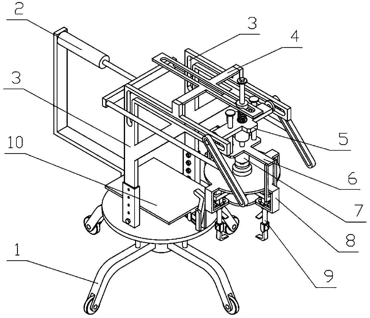
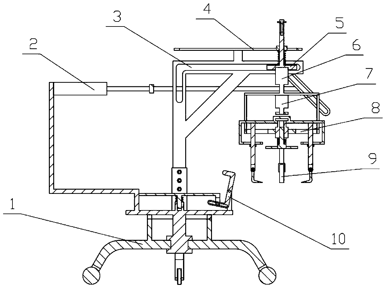
[0039] Combine below Figure 1-15 Describe this embodiment, an unloading rack for logistics transportation, including a device bracket 1, a pushing mechanism 2, a transport bracket 3, a limit bracket 4, a transport mechanism 5, a lifting mechanism 6, a power mechanism 7, an unloading bracket 8 and an unloading mechanism 9,
[0040] The push plate II9-8 can be in contact with the upper surface of the goods to be unloaded. Under the push of the lifting mechanism 6, the push plate II9-8 squeezes the compression spring I to push the unloading mechanism 9 to slide on the unloading bracket 8, so that the unloading The mechanism 9 and the power mechanism 7 perform friction transmission, the power mechanism 7 drives the friction wheel Ⅱ 9-2 arranged on the unloading mechanism to rotate, the friction wheel Ⅱ 9-2 drives the unloading threaded disc 9-1 to rotate, and the unloading threaded disc 9-1 passes through the vortex The threads drive the four clamping rods 9-9 to slide closer to...
specific Embodiment approach 2
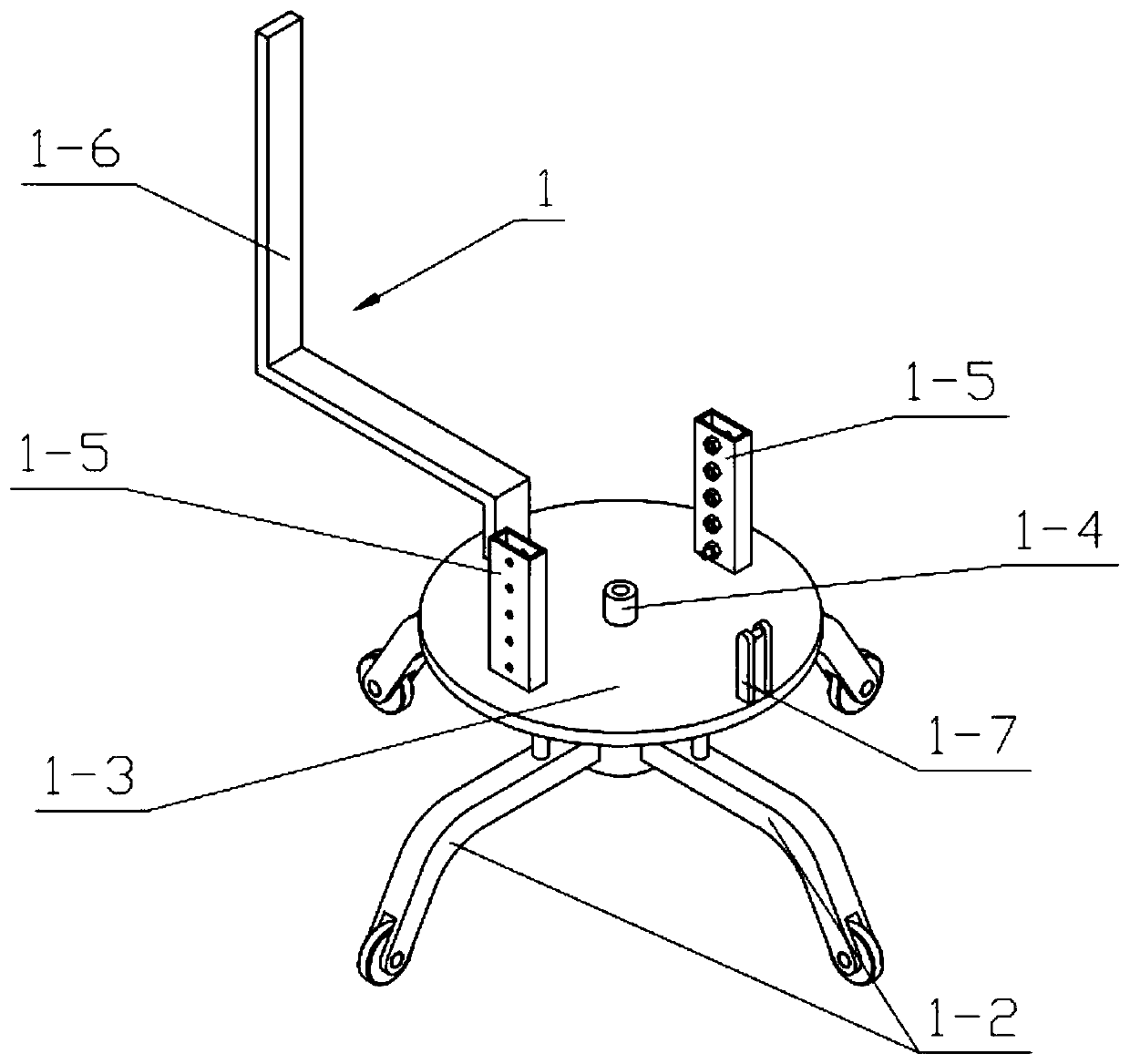
[0044] Combine below Figure 1-15 Describe this embodiment, this embodiment will further explain Embodiment 1, the device bracket 1 includes a rotating bracket 1-1, a moving wheel frame 1-2, a bottom plate 1-3, a sliding cylinder 1-4, and an adjusting bracket 1-5 , support plate Ⅰ 1-6 and swing bracket 1-7, rotation bracket 1-1 is uniformly fixedly connected with four moving wheel frames 1-2 in the circumferential direction, rotation bracket 1-1 is connected with base plate 1-3, base plate 1 The left and right sides of the upper end of -3 are fixedly connected with adjustment brackets 1-5, the two adjustment brackets 1-5 are provided with a plurality of adjustment holes I, and the rear side of the upper end of the bottom plate 1-3 is fixedly connected with support plates I1-6 , the front side of the upper end of the base plate 1-3 is fixedly connected with a swing bracket 1-7, and the center of the upper end of the base plate 1-3 is fixedly connected with a sliding cylinder 1-...
specific Embodiment approach 3
[0046] Combine below Figure 1-15 Describe this embodiment, this embodiment will further explain the second embodiment, the push mechanism 2 includes an electric telescopic rod I2-1, a push plate I2-2 and an inclined plate 2-3, and the electric telescopic rod I2-1 is fixedly connected to On the support plate I1-6, the push plate I2-2 is fixedly connected to the telescopic end of the electric telescopic rod I2-1, and both sides of the push plate I2-2 are fixedly connected with inclined plates 2-3; when the cargo clamping is completed, start Electric telescopic rod Ⅰ2-1, the telescopic end of the electric telescopic rod Ⅰ2-1 moves to the side of the support plate Ⅰ1-6, and the telescopic end of the electric telescopic rod Ⅰ2-1 drives the two inclined plates 2-3 to the side of the support plate Ⅰ1-6 To move, the two inclined plates 2-3 drive the transport mechanism 5 to slide in the two L-shaped transport grooves 3-2, and the transport mechanism 5 drives the lifting mechanism 6, ...
PUM
 Abstract
Description
Claims
Application Information
 - R&D Engineer
- R&D Manager
- IP Professional
- Industry Leading Data Capabilities
- Powerful AI technology
- Patent DNA Extraction
Browse by: Latest US Patents, China's latest patents, Technical Efficacy Thesaurus, Application Domain, Technology Topic, Popular Technical Reports.
© 2024 PatSnap. All rights reserved.Legal|Privacy policy|Modern Slavery Act Transparency Statement|Sitemap|About US| Contact US: help@patsnap.com


