
Railway vehicle and air inlet device thereof

A technology for air intake devices and rail vehicles, which is applied in the field of rail vehicles and can solve problems such as increased negative pressure difference, impact on vehicle operation safety, and reduced air volume

Active Publication Date: 2019-08-23
ZHUZHOU ELECTRIC LOCOMOTIVE CO
View PDF13 Cites 1 Cited by
  • Summary
  • Abstract
  • Description
  • Claims
  • Application Information

AI Technical Summary

Problems solved by technology

[0003] The air inlet of the existing air intake device is usually located on the upper surface of the device. When the vehicle is running, the air flow rate on the upper surface is faster, thereby generating a negative pressure, and as the speed of the vehicle increases, the negative pressure difference will continue Increase, the existence of negative pressure difference causes the air volume entering the air inlet device from the air inlet on the upper surface to decrease
The instability of the air intake will directly affect the cooling effect of the air conditioning and ventilation system, thus affecting the working status of the components in the vehicle that need ventilation and cooling, and affecting the operation safety of the vehicle

Method used


Image

  • Railway vehicle and air inlet device thereof
  • Railway vehicle and air inlet device thereof
  • Railway vehicle and air inlet device thereof

Examples


Embodiment Construction

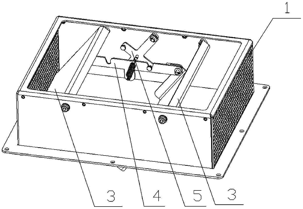
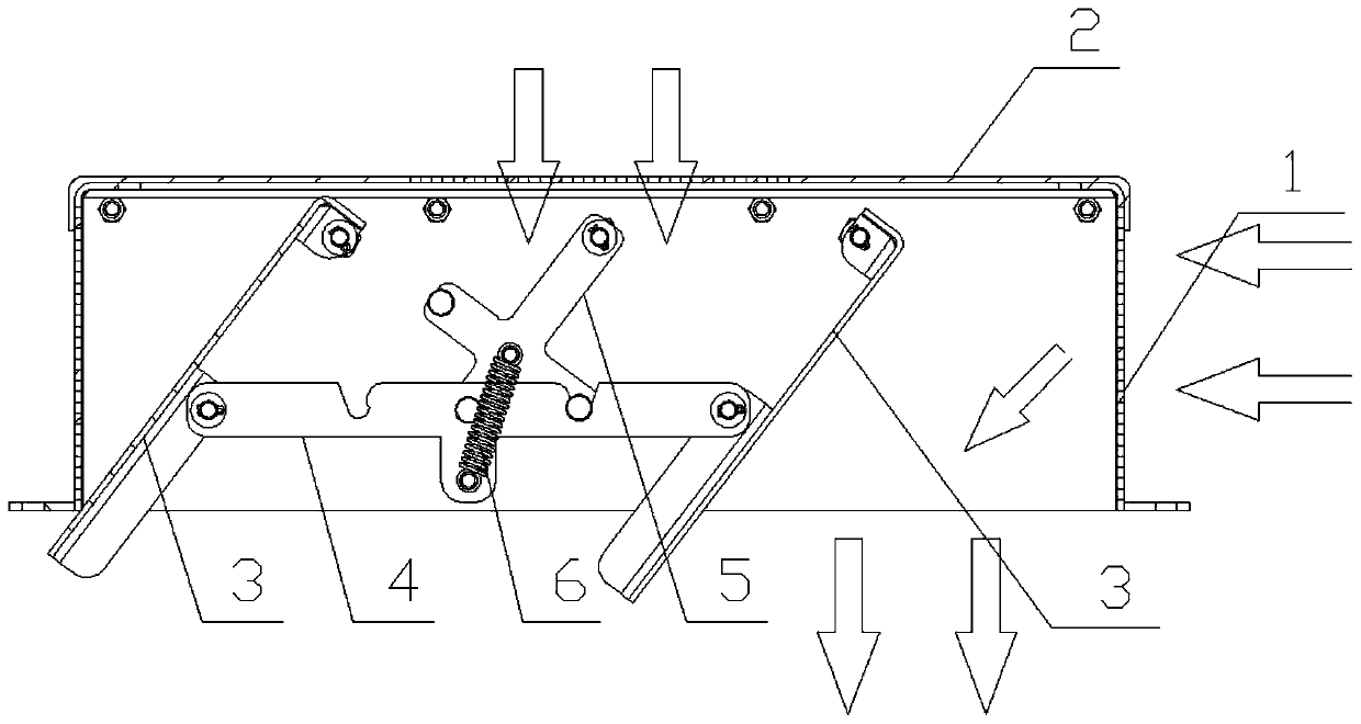
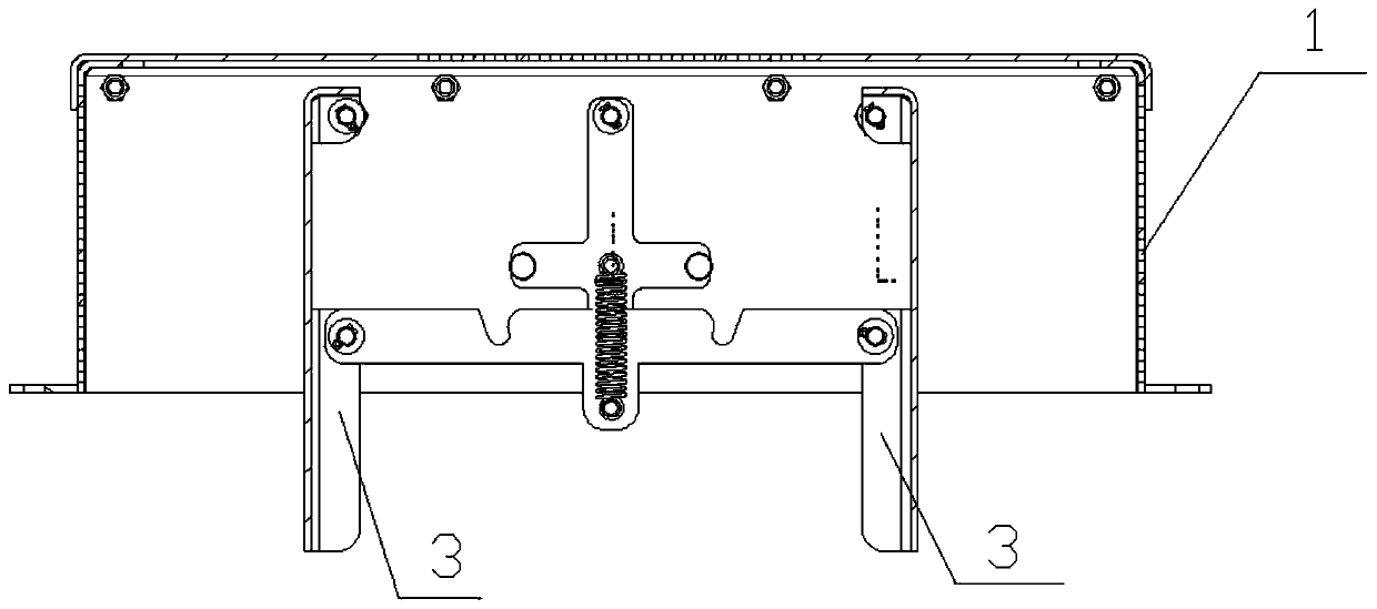
[0028] The core of the present invention is to provide an air intake device for rail vehicles. When the vehicle moves forward through the deflector, the air flow enters the air inlet of the air conditioner from the end air inlet at the front end, avoiding the instability of the air intake caused by the negative pressure difference and improving safety. sex. Another core of the present invention is to provide a rail vehicle comprising the above air intake device.

[0029] In order to enable those skilled in the art to better understand the solution of the present invention, the present invention will be further described in detail below in conjunction with the accompanying drawings and specific embodiments.

[0030] Please refer to Figure 1 to Figure 10 , figure 1 It is a structural schematic diagram of a specific embodiment of the air inlet device provided by the present invention; figure 2 It is a schematic diagram of one end air intake state of a specific embodiment of ...


PUM


Abstract

The invention discloses an air inlet device of a railway vehicle. The air inlet device comprises an air inlet way body externally arranged on the top of the vehicle, the lower portion of the air inletway body communicates with an air conditioner air inlet, and end portion air inlets are formed in the two ends, in the vehicle running direction, of the air inlet way body. Flow guiding plates are arranged in the air inlet way body. When the vehicle advances, airflow enters the air inlet way body from the end portion air inlet located in the front end and pushes the flow guiding plates to move sothat the end portion air inlet located in the rear end can be shielded, and the end portion air inlet located in the front end conducts the air conditioner air inlet. Top air inflow is changed into front air inflow, the negative pressure difference cannot be generated, the phenomenon that according to an air inlet device, during vehicle running, the negative pressure is formed nearby the surface,air inflow cannot be achieved or the air inflow volume is small is effectively avoided, the air inflow volume is guaranteed, and the ventilating and cooling effect of an air conditioner ventilation system is guaranteed. Meanwhile, since the air inlets are formed in the front end and the rear end, when the vehicle advances towards the two ends, normal air inflow can be guaranteed. The invention further discloses the railway vehicle comprising the above air inlet device.

Description

technical field [0001] The invention relates to the field of rail vehicles, in particular to an air intake device for rail vehicles. Furthermore, the invention also relates to a rail vehicle comprising the above-mentioned air intake device. Background technique [0002] At present, rail vehicles are equipped with air-conditioning systems to achieve ventilation in the vehicle interior and improve comfort and safety. The air-conditioning system needs to be equipped with an air intake device for the entry of outside air. At present, the air intake device of a rail vehicle is usually installed on the surface of the vehicle, such as the roof, the side wall of the car body, and the side suspension beam. [0003] The air inlet of the existing air intake device is usually located on the upper surface of the device. When the vehicle is running, the air flow rate on the upper surface is faster, thereby generating negative pressure, and as the vehicle running speed increases, the nega...

Claims


Application Information

Patent Timeline
IPC IPC(8): B61D27/00
CPCB61D27/009
Inventor 李希宁丁伟民李超朱茂华刘强
Owner ZHUZHOU ELECTRIC LOCOMOTIVE CO
Learn More