Electric cabinet base structure and installation and adjustment method thereof

An electrical cabinet and adjusting seat technology, which is applied in the field of electrical cabinets, can solve the problems of inability to adjust the state of universal casters at the same time, poor braking stability, and easy aging due to environmental influences.

Active Publication Date: 2019-08-16
安徽恒电电气设备有限公司
View PDF3 Cites 5 Cited by
  • Summary
  • Abstract
  • Description
  • Claims
  • Application Information

AI Technical Summary

Problems solved by technology

[0004] 1. It is necessary to adjust the universal casters one by one to control the state of each universal caster, to move or brake the cabinet, which is very troublesome, and it is impossible to adjust the status of all universal casters at the same time;
[0005] 2. The traditional universal caster braking method is through rubber friction braking, so the braking stability is poor;
[0006] 3. Traditional swivel casters are exposed to the outside for a long time under braking, and are easily affected by the environment and aging

Method used


Image

  • Electric cabinet base structure and installation and adjustment method thereof
  • Electric cabinet base structure and installation and adjustment method thereof
  • Electric cabinet base structure and installation and adjustment method thereof

Examples


Embodiment Construction

[0056] The following are specific embodiments of the present invention and in conjunction with the accompanying drawings, the technical solutions of the present invention are further described, but the present invention is not limited to these embodiments.

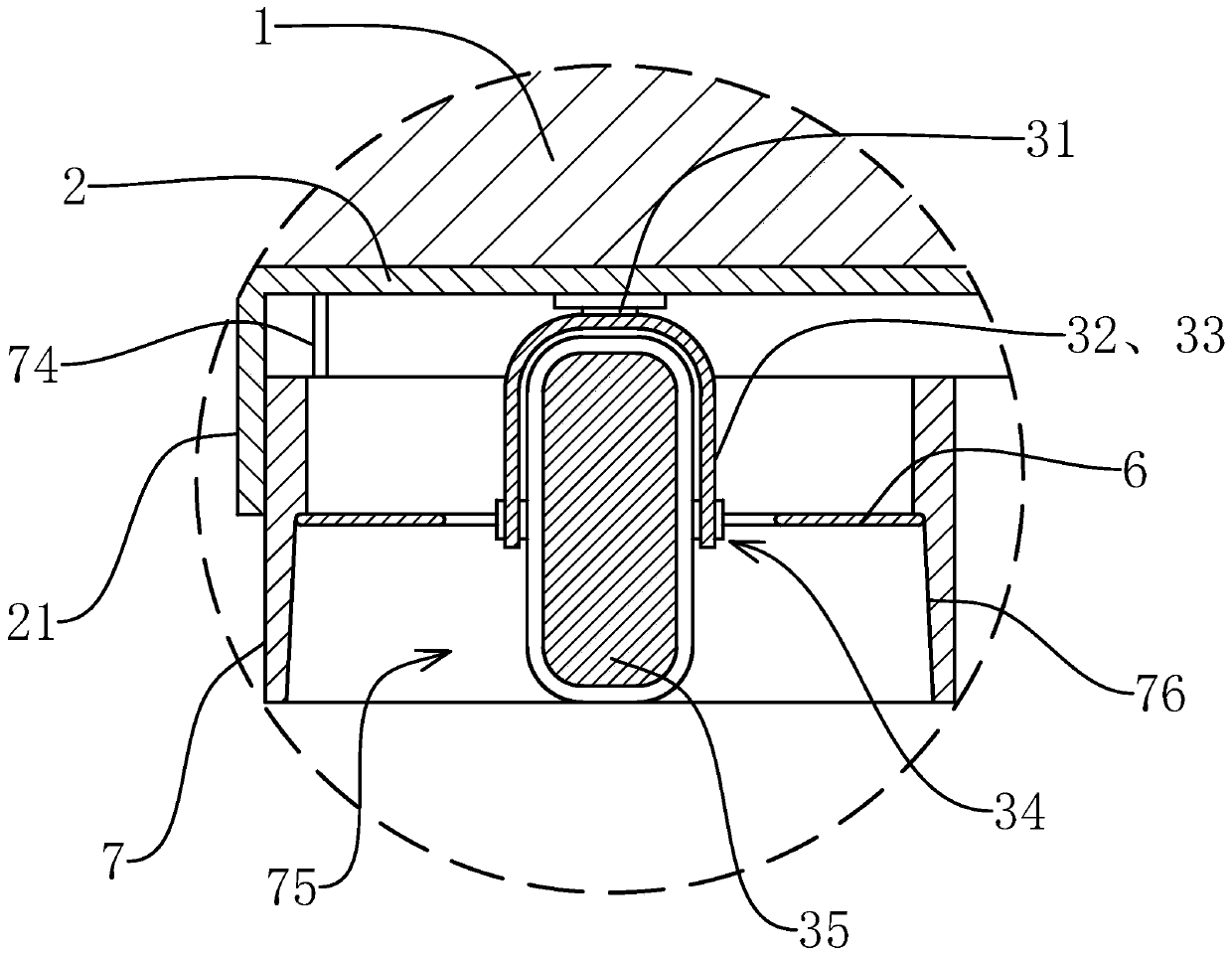
[0057] Such as Figure 1-7 As shown, the base structure of an electrical cabinet of the present invention is used to be installed on the bottom of the cabinet body 1 of the electrical cabinet, and is used to move the cabinet body 1. Several swivel casters 3, the swivel caster 3 comprises housing 32, and housing 32 is connected with base plate 2 by rotating member 31, also comprises the roller 35 that is connected with housing 32 by rolling member 34, and roller 35 can respectively surround the rotation axis of rotating member 31 The axis of rotation of the rotating and rolling element 34 rolls, and the axis of rotation of the rotating element 31 is perpendicular to the base plate 2, and is perpendicular to the axis of rota...


PUM


Abstract

The invention provides an electric cabinet base structure and an installation and adjustment method thereof, belongs to the field of electric cabinets, and solves the problem that the state of multiple casters cannot be adjusted simultaneously. The electric cabinet base structure comprises a bottom plate with universal feet connected on the bottom surface. Each universal foot comprises a housing.The housing is connected with the bottom plate by a rotating member. The electric cabinet base structure further comprises a roller connected with the housing through a rolling member. The housing comprises two housing plates. A shaft hole is arranged in the roller. The two ends of the shaft hole are provided with shaft grooves. The electric cabinet base structure further comprises a shaft tube fixed with the housing plates. The shaft tube is arranged in the shaft grooves in a penetration way. The electric cabinet base structure further comprises a shaft rod arranged in the shaft tube in a penetration way. The wall of the shaft hole is provided with a tooth groove. The wall of the shaft rod is provided with teeth. The electric cabinet base structure further comprises an adjusting rod whichis connected with the shaft rod through a connecting rod. The electric cabinet base structure further comprises an adjusting base which is provided with adjusting holes. The universal casters are arranged in the adjusting holes. The walls of the adjusting holes are provided with adjusting grooves. The electric cabinet base structure further comprises a reset spring arranged in the shaft hole. According to the base structure, the state of all the universal casters can be quickly adjusted and the universal casters can be completely braked.

Description

technical field [0001] The invention belongs to the technical field of electric cabinets, and relates to an electric cabinet base structure and an installation and adjustment method thereof. Background technique [0002] In the field of automation, there are more and more electrical equipment and related cables. These equipment need to be installed centrally in the electrical cabinet. The electrical cabinet should not only play the role of a switchboard, but also serve as an installation carrier for various large-scale equipment. [0003] Several universal casters are usually installed on the base of the existing electrical cabinet, and the universal casters are used to facilitate the movement of the cabinet, but the traditional base has the following disadvantages: [0004] 1. It is necessary to adjust the universal casters one by one to control the state of each universal caster, to move or brake the cabinet, which is very troublesome, and it is impossible to adjust the st...

Claims


Application Information

Patent Timeline
IPC IPC(8): H05K5/02
CPCH05K5/0234
Inventor 林玉平
Owner 安徽恒电电气设备有限公司
Why Eureka
Try Eureka