
Management method and system for wireless sensors of power environment monitoring system

A power environment monitoring and wireless sensor technology, which is applied in specific environment-based services, power management, wireless communication, etc. Unification and other issues to achieve the effect of reducing maintenance workload

Pending Publication Date: 2019-08-16
湖南晟睿景智能科技有限公司
View PDF6 Cites 8 Cited by
  • Summary
  • Abstract
  • Description
  • Claims
  • Application Information

AI Technical Summary

Problems solved by technology

[0006] The present invention provides a management method and system for wireless sensors of a power environment monitoring system, which are used to solve the problem that the power consumption of the wireless sensors of the power environment monitoring system is too fast and the time when the power consumption of multiple wireless sensors is not uniform, which is inconvenient for replacement operations technical issues

Method used

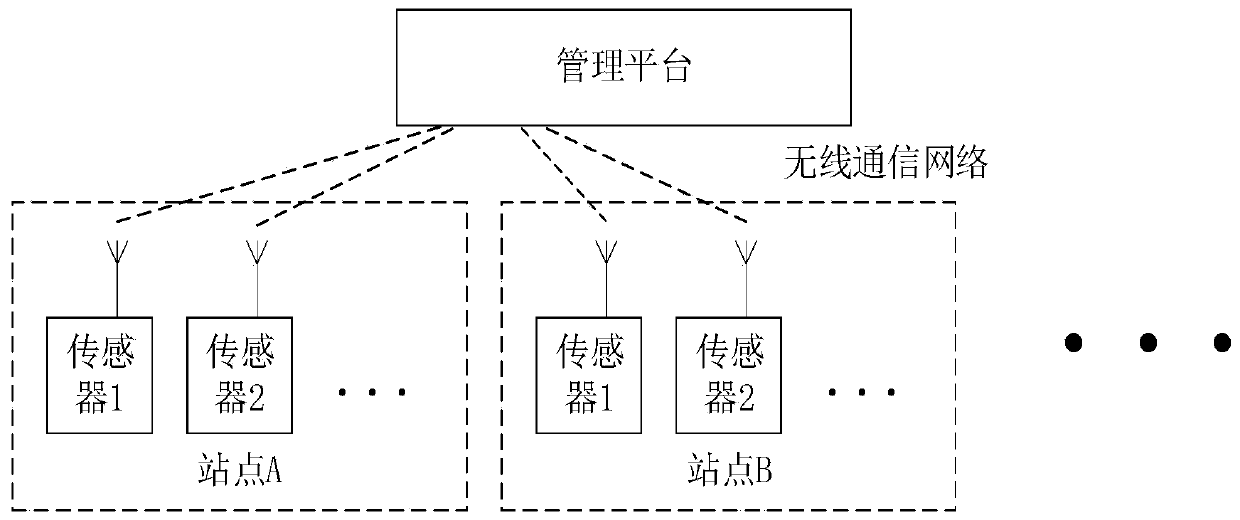
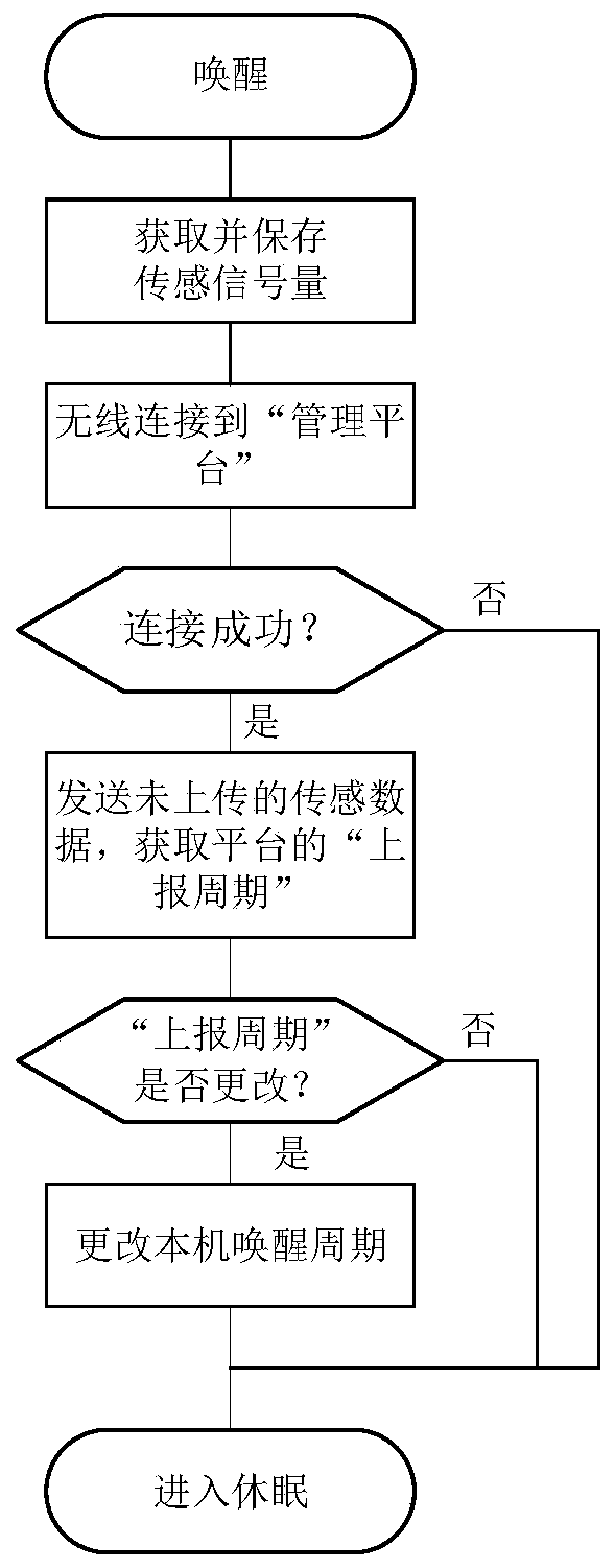

Image

  • Management method and system for wireless sensors of power environment monitoring system
  • Management method and system for wireless sensors of power environment monitoring system
  • Management method and system for wireless sensors of power environment monitoring system

Examples


Embodiment 1

[0053] In this embodiment, the temperature and humidity sensor consumes 10uA of power in the dormant state; in the acquisition state, it takes 1 second to collect data once and the working current is 1mA; in the communication state, it sends data (temperature and humidity values) to the platform and receives setting information (reporting period) The working current and duration are: 50mA and 10s, respectively. The values ​​used in this embodiment are the average values ​​obtained from multiple tests under various conditions during the research and development stage for illustration. The working mode of the wireless sensor is in Figure 4 state switch, and follow the image 3 process to work.

[0054] The power evaluation and frequency adjustment are performed according to the above method:

[0055] The current record of sensor #001 (temperature and humidity sensor, battery power is 1000mAh, nominal voltage 3.6V, factory voltage 3.66V) on the platform: 100 days since the us...

Embodiment 2

[0067] Compared with Embodiment 1, this embodiment can be used for more accurate power consumption calculation, can divide states in more detail, and can measure time more accurately. Figure 5 It is the working process of the wireless sensor in this embodiment. In this embodiment, power consumption: 10uA in sleep state; in acquisition state, it takes 1s to collect data once, and the working current is 1mA; in communication state, send data to the platform (data includes temperature value , Humidity value, wireless signal strength, wireless communication duration) and the working current of receiving setting information are: 50mA when the wireless signal is good, 60mA when the wireless signal is normal, and 70mA when the wireless signal is poor. The duration of the communication process is determined by the sensor Record and upload; pre-sleep state 30mA and 1s after communication is completed.

[0068] The wireless signal strength has specific parameter values, and the platfor...


PUM


Abstract

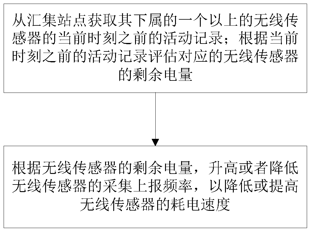
The invention discloses a management method and system for the wireless sensors of a power environment monitoring system. The method comprises the steps of obtaining the activity records of more thanone wireless sensor subordinate to a collection site before the current moment from the collection site; evaluating the residual electric quantity of the corresponding wireless sensor according to theactivity record before the current moment; and according to the residual electric quantity of the wireless sensor, increasing or decreasing the acquisition and reporting frequency of the wireless sensor so as to reduce or increase the power consumption speed of the wireless sensor. According to the invention, the residual electric quantity of the sensor can be estimated, and the power consumptioncompletion time of the wireless sensors subordinate to the same collection station is basically consistent, so that the maintenance workload of the workers of the wireless communication battery powersupply sensors can be reduced.

Description

technical field [0001] The invention relates to the field of signal acquisition, in particular to a wireless sensor management method and system that can be used in a power environment monitoring system in a wireless sensor-based signal acquisition system in industrial and agricultural production and construction. Background technique [0002] In the power environment monitoring system using wireless technology, the wireless sensor is powered by a battery, and the battery power is limited. In actual use, it is usually necessary to know how long the battery of the sensor can be used. Since most of the batteries used in sensors are disposable industrial batteries, the discharge voltage is very stable when working. Even if half of the power is consumed, the voltage can still remain the same as when it is fully charged. When the voltage drops significantly, it means that the battery is about to run out. do. Therefore, judging the battery power by voltage is often not feasible. ...

Claims


Application Information

Patent Timeline
Patent Type & Authority Applications(China)
IPC IPC(8): H04W4/38H04W52/02
CPCH04W4/38H04W52/0261H04W52/0229Y02D30/70
Inventor 温兴清孙杰
Owner 湖南晟睿景智能科技有限公司
Learn More