A separate electrical switch box with fast power on and off structure

A power-on/off-separation technology, applied in the direction of electric switches, electrical components, circuits, etc., can solve the problems of single structure of electrical switch boxes, increase the risk of electric shock for workers, and cumbersome electrical components, so as to facilitate installation and maintenance and save work Time, the effect of quick power-off and power-on

Inactive Publication Date: 2021-01-26
QIQIHAR INST OF ENG
View PDF6 Cites 0 Cited by
  • Summary
  • Abstract
  • Description
  • Claims
  • Application Information

AI Technical Summary

Problems solved by technology

[0002] The electrical switch box is a very common electrical device. There is a cavity for placing electrical components in the electrical switch box, which provides a centralized installation position for electrical switches and has a certain protective effect on electrical components; but the traditional electrical switch box structure It is relatively simple, and there is only one inner cavity for installing electrical components inside. During disassembly and maintenance, workers must cut off the power of the external master switch connected to the device before disassembling and overhauling the electrical components inside the electrical switch box. , due to the installation and maintenance of the electrical components inside the electrical switch box, repeated inspections after power-on are required, so that workers have to repeatedly operate back and forth between the electrical switch box and the main switch, even if the installation and maintenance of electrical components It becomes cumbersome and wastes a lot of working time. Sometimes workers increase the risk of electric shock for the convenience of direct live operation. Therefore, we propose a separate electrical switch box with a fast on-off structure

Method used


Image

  • A separate electrical switch box with fast power on and off structure
  • A separate electrical switch box with fast power on and off structure
  • A separate electrical switch box with fast power on and off structure

Examples


Embodiment Construction

[0023]The technical solutions in the embodiments of the present invention will be clearly and completely described below in conjunction with the accompanying drawings in the embodiments of the present invention. Obviously, the described embodiments are only a part of the embodiments of the present invention, rather than all the embodiments. Based on the embodiments of the present invention, all other embodiments obtained by those of ordinary skill in the art without creative work shall fall within the protection scope of the present invention.

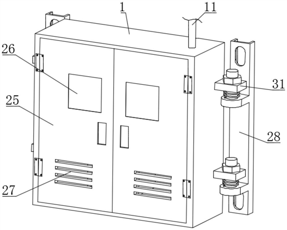
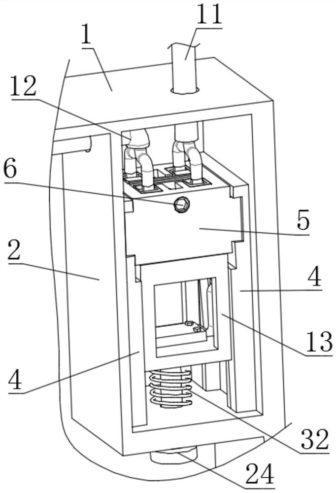
[0024]SeeFigure 1-10, The present invention provides a technical solution: a separate electrical switch box with a quick power-on and power-off structure, comprising a box body 1 inside which is fixedly installed an inner box 2 and a plurality of electrical components 3, so The inner two side walls of the inner box 2 are fixedly connected with side plates 4, and a base 5 is fixedly clamped between the two side plates 4. The material of the base...


PUM


Abstract

The invention discloses a separated electrical switch box with a fast power on and off structure, which comprises a box body, an inner box is fixedly installed inside the box body, and side plates are fixedly connected to both inner side walls of the inner box, two The base is fixedly clamped between the side plates, and a plurality of conductive blocks are fixedly connected to the base. The lower side of the conductive block is fixedly connected with a copper clip through a copper column, and the bottom of the base is slidingly connected between the two side plates. There is a lifting frame, the upper side of the lifting frame is slidably connected to a top plate through the first spring, and a plurality of copper blocks are fixedly connected to the upper surface of the top plate, and the two ends of the copper blocks are respectively clamped inside two copper clips. Push the rod to raise the lifting frame, and the sliding rod is stuck on the hook with the lifting frame, so as to achieve the purpose of fast power on, avoiding the repeated back and forth operation between the electrical switch box and the main switch knife for workers, which is convenient for installation and operation. Access the electrical components inside the unit.

Description

Technical field[0001]The present invention relates to the technical field of electrical switches, in particular to a separated electrical switch box with a quick-on-off structure.Background technique[0002]The electrical switch box is a very common electrical device. There is a cavity for placing electrical components in the electrical switch box, which provides a centralized installation position for the electrical switch, and has a certain protective effect on the electrical components; but the traditional electrical switch box structure It is relatively simple, with only one inner cavity for installing electrical components. During disassembly and inspection, workers must cut off the power of the external switch connected to the device before disassembling and repairing the electrical components inside the electrical switch box , As the electrical components inside the electrical switch box are installed and overhauled repeatedly after power-on, workers have to repeatedly operate ...

Claims


Application Information

Patent Timeline
Patent Type & Authority Patents(China)
IPC IPC(8): H01H9/02H01H1/58
CPCH01H1/5844H01H9/02
Inventor 张磊刘春媛李野丁向朝关娜李阁
Owner QIQIHAR INST OF ENG
Why Eureka
Try Eureka