
Adjusting method and projection method of adjustable speckle pattern

An adjustment method and pattern technology, applied in the field of D imaging, can solve the problems of inability to accurately identify the measured object, insufficient depth information, single speckle pattern, etc.

Active Publication Date: 2019-08-16
SUNNY OPTICAL ZHEJIANG RES INST CO LTD
View PDF6 Cites 9 Cited by
  • Summary
  • Abstract
  • Description
  • Claims
  • Application Information

AI Technical Summary

Problems solved by technology

[0004] However, the speckle structured light projector of the existing speckle structured light device can usually only project a fixed speckle pattern, that is, the speckle pattern projected by the speckle structured light projector is single and cannot be changed, so that the The depth information obtained by the existing speckle structured light equipment is not comprehensive or deviated, which affects the measurement accuracy of the existing speckle structured light equipment, and the quality of the obtained depth image is not good, so it cannot meet the needs of the market
[0005] In addition, the speckle structured light projector is also easily affected by factors such as working distance, ambient temperature, or / and complex scenes, which further reduces the measurement accuracy of the existing speckle structured light device, and the quality of 3D imaging bad
For example, for scenes with complex and concentrated features (that is, the feature parts of the measured object are relatively concentrated), the speckle structured light projector can only project according to the preset speckle pattern, which may cause the feature of the measured object The density of the speckle pattern in some places is not enough to accurately measure the specific characteristics of the measured object, that is to say, the three-dimensional information of the measured object is not fully acquired, so that the existing speckle structured light equipment cannot truly Restore the three-dimensional image of the measured object, or cannot accurately identify the measured object

Method used


Image

  • Adjusting method and projection method of adjustable speckle pattern
  • Adjusting method and projection method of adjustable speckle pattern
  • Adjusting method and projection method of adjustable speckle pattern

Examples


Embodiment Construction

[0058] The following description serves to disclose the present invention to enable those skilled in the art to carry out the present invention. The preferred embodiments described below are only examples, and those skilled in the art can devise other obvious variations. The basic principles of the present invention defined in the following description can be applied to other embodiments, variations, improvements, equivalents and other technical solutions without departing from the spirit and scope of the present invention.

[0059] Those skilled in the art should understand that in the disclosure of the present invention, the terms "vertical", "transverse", "upper", "lower", "front", "rear", "left", "right", " The orientation or positional relationship indicated by "vertical", "horizontal", "top", "bottom", "inner", "outer", etc. is based on the orientation or positional relationship shown in the drawings, which are only for the convenience of describing the present invention...


PUM


Abstract

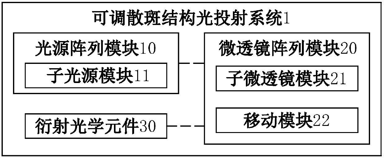
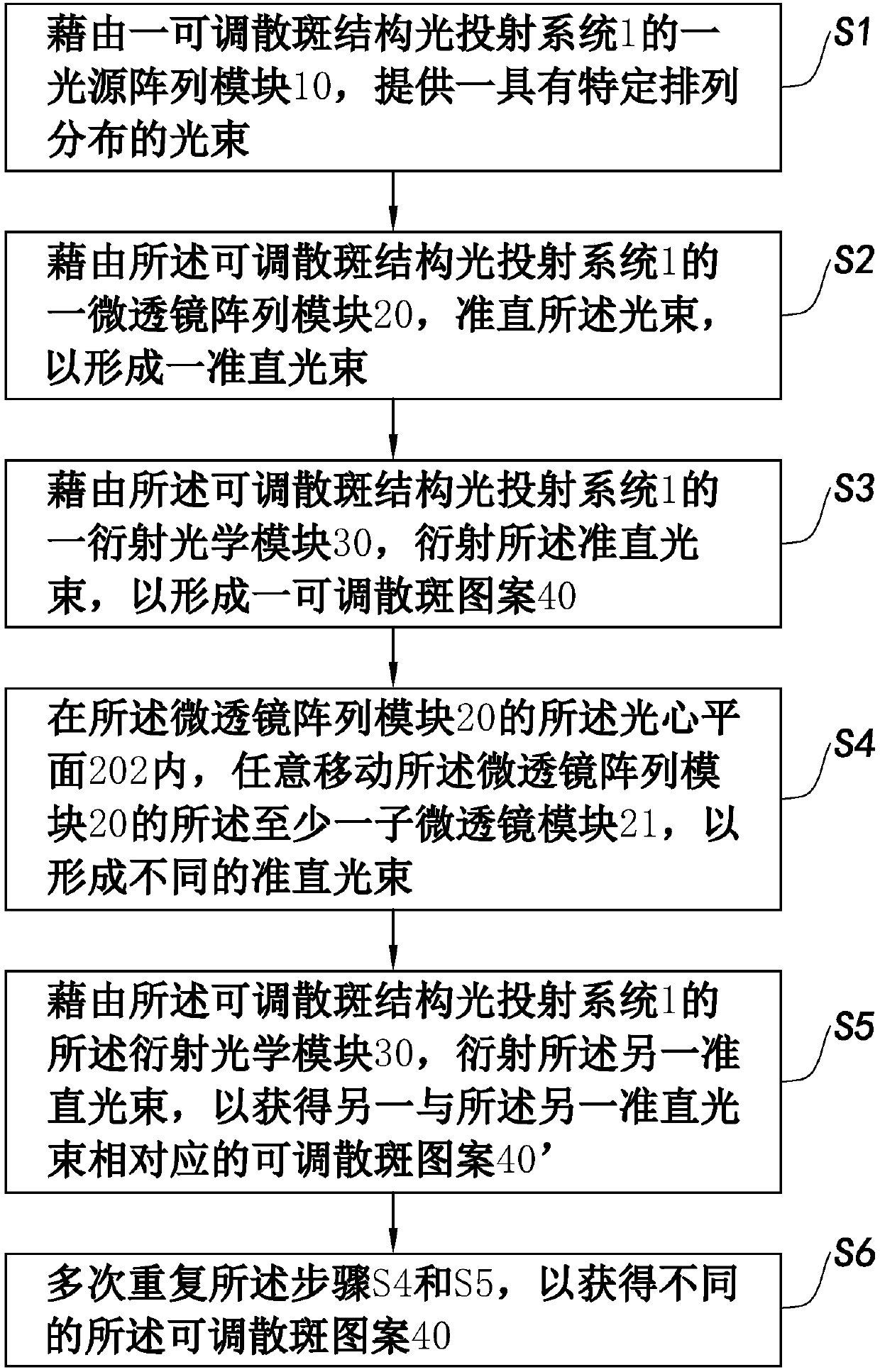
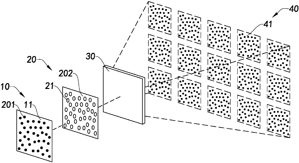
The invention discloses an adjusting method and projection method of an adjustable speckle pattern. The adjusting method of the adjustable speckle pattern comprises the step of moving at least one sub-microlens module in a microlens array module to adjust a position of the at least one sub-microlens module in an optic center plane of the microlens array module, so as to obtain different adjustablespeckle patterns, thereby calibrating and measuring multiple sets of speckle patterns for the entire space.

Description

technical field [0001] The present invention relates to the technical field of 3D imaging, and more particularly relates to an adjustment method of an adjustable speckle pattern and a projection method thereof. Background technique [0002] Optics has always been the highlight of technological innovation. Although the traditional camera has experienced the doubling of pixels and numbers in the 2D era, the optical camera of this traditional camera has always stayed at the two-dimensional level of pixels and light sensitivity. With the rapid development of 3D imaging technology, 3D imaging technology can realize the superposition of pixel depth of field on the basis of two dimensions, and then obtain the third-dimensional information (geometric data such as size and distance) in the physical world lost by 2D plane imaging technology. ) to generate a depth image, which is used to identify the three-dimensional coordinate information of each point in the field of view, so as to ...

Claims


Application Information

Patent Timeline
Patent Type & Authority Applications(China)
IPC IPC(8): G02B27/09G02B27/42G02B27/48
CPCG02B27/0933G02B27/0961G02B27/4205G02B27/48
Inventor 郝希应周炳张晓伟吴治平胡增新
Owner SUNNY OPTICAL ZHEJIANG RES INST CO LTD
Learn More