Lens component of intelligent image measurement instrument
A technology of image measuring instrument and lens assembly, which is applied in the detection field, can solve problems affecting the performance of cables or optical cables, production profit decline, breakdown, etc., and achieve the effect of improving coverage and flexibility
- Summary
- Abstract
- Description
- Claims
- Application Information
AI Technical Summary
Problems solved by technology
Method used
Image
Examples
Embodiment 1
[0020] see figure 1 , in an embodiment of the present invention, a lens assembly of an intelligent image measuring instrument includes a fixed structure, a camera 3 and a lens 4 mounted on the fixed structure, the lens 4 is assembled below the shooting position of the camera 3, and the fixed structure It includes a mounting rod 2 and a mounting plate 1 fixed on the lower part of the mounting rod 2 by riveting or welding, and the camera 3 is connected and fixed on the mounting plate 1 by riveting or the like.
[0021] Such an arrangement can connect the entire structure to the detection structure in a fixed or movable manner through the installation rod 2, so that when observing the test sample, the observation and detection angle position of the camera 3 and the lens 4 can be controlled and adjusted through the installation rod 2, thereby Realize intelligent measurement.
Embodiment 2
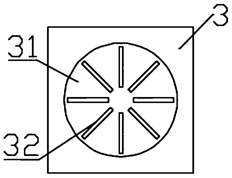
[0023] see Figure 2~3 , in the embodiment of the present invention, in order to improve the overall observation flexibility of the device, a lens assembly of an intelligent image measuring instrument, on the basis of embodiment 1, the side of the placement plate 1 is arranged in a circular array with multiple sets of blind A hole 11, the blind hole 11 is provided with a limit protrusion 12 through a spring elastic connection, the end of the limit protrusion 12 is semi-spherical and extends out of the blind hole 11, and the limit protrusion 12 and the blind hole 11 slide Cooperating, the circular periphery formed by the blind hole 11 is concentrically provided with a rotating bearing 13, the rotating bearing 13 is embedded in the end surface of the setting plate 1 and is rotatably connected with the setting plate 1, and the rotating bearing 13 is connected to the side of the camera 3 .
[0024] The camera 3 is rotationally connected to the mounting plate 1 through a rotating ...
PUM
 Abstract
Description
Claims
Application Information
 - Generate Ideas
- Intellectual Property
- Life Sciences
- Materials
- Tech Scout
- Unparalleled Data Quality
- Higher Quality Content
- 60% Fewer Hallucinations
Browse by: Latest US Patents, China's latest patents, Technical Efficacy Thesaurus, Application Domain, Technology Topic, Popular Technical Reports.
© 2025 PatSnap. All rights reserved.Legal|Privacy policy|Modern Slavery Act Transparency Statement|Sitemap|About US| Contact US: help@patsnap.com


