An antifreeze method for air intake shafts of underground mines in alpine regions

A technology of air intake in alpine regions, applied in the ventilation of mines/tunnels, mining equipment, earthwork drilling and mining, etc., can solve problems affecting occupational health and safety, limited installation space, high energy consumption for preheating and antifreeze, and achieve The effect of economical and reasonable frozen well problem, overcoming the limitation of installation location, and solving the problem of frozen well

Active Publication Date: 2020-11-06
SINOSTEEL MAANSHAN INST OF MINING RES +1
View PDF1 Cites 0 Cited by
  • Summary
  • Abstract
  • Description
  • Claims
  • Application Information

AI Technical Summary

Problems solved by technology

[0007] The purpose of the present invention is to solve the problem of freezing well disasters in the auxiliary shafts of underground mines and the air intake shafts of the air intake shafts in the alpine regions in winter, and the existing technical solutions have high energy consumption for preheating and antifreezing, and the surface of the auxiliary shaft and the inside of the shaft The location of the installation space is limited, the process of conveying hot air affects the thermal comfort of personnel, affects occupational health and safety and other technical problems, as well as the potential heat potential contained in the anti-air flow, and provides an antifreeze method for the air intake shaft of underground mines in alpine regions. This method can realize the normal ventilation of the air inlet shaft in diurnal and night-time periods and anti-freezing in the anti-wind state according to the characteristics of the change in the air flow direction of the ventilation system caused by the change in the temperature difference between day and night in the underground mine in the alpine region.

Method used


Image

  • An antifreeze method for air intake shafts of underground mines in alpine regions

Examples


Embodiment Construction

[0027] In order to better describe the present invention, a kind of antifreeze method for the air intake shaft of an underground mine in an alpine region of the present invention will be further described in detail below in conjunction with the accompanying drawings.

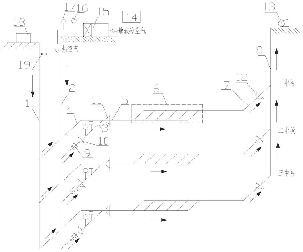
[0028] Depend on figure 1 The schematic diagram of the structural arrangement of a kind of antifreeze method for the air intake shaft of underground mines in the shown present invention shows that the auxiliary shaft 1, the air intake shaft 2, and the return air shaft 8 are vertically arranged, and the middle section of the air inlet lane 5 is arranged horizontally , the auxiliary well stone door 4 and the air inlet lane 3 are arranged obliquely, the auxiliary shaft 1 and the middle air inlet lane 5 are connected through the auxiliary shaft stone gate 4, and the air inlet shaft 2 and the middle air inlet lane 5 are connected through the air inlet shaft The joint roadway 3 is connected, and the fresh shunt flow f...


PUM


Abstract

The invention discloses an anti-freezing method for an entering wind shaft of an underground mine of a high and cold area. An adopted anti-freezing system is constituted by a preheating unit (15), anair curtain unit (18), an annular jet flow wind gap (19), a fan device, a wind door, sensors and a PLC control system (14) which are combined; the preheating unit (15) is arranged on the wellhead surface of an entering wind well (2), and the air curtain unit (18) is arranged on the wellhead surface of an auxiliary well (1); the annular jet flow wind gap (19) is formed in a shaft of the auxiliary well (1); and the PLC control system (14) is connected with all the sensors, receives data collected by all the sensors and conducts regulation control on operation of the preheating unit (15), the aircurtain unit (18), a fan and the wind door. According to the characteristic that the day and night temperature difference change of the underground mine of the high and cold area causes change of thewind flow direction of a ventilation system, normal ventilation and inverted ventilation state freeze prevention of the entering wind shaft in day and night divided periods are achieved, preheating energy consumption of a preheating system is reduced remarkably, personnel heat comfort is improved, occupational health and safety are achieved, the requirement for the wind required amount of ventilation is met, and the problem of well freezing of the shaft of the auxiliary well is also economically and reasonably solved.

Description

technical field [0001] The invention belongs to the technical field of mine ventilation and environmental protection, and specifically relates to a method for solving the problem of freezing shafts of mine air intake shafts in alpine regions, and is particularly suitable for antifreezing of air intake shaft shafts where ventilation systems enter air through air intake shafts and auxiliary shafts. Background technique [0002] The air intake shafts of underground mines mainly include auxiliary shafts and air intake shafts. In mines in high-altitude and cold regions, about 80% of underground mines have air intake shafts that suffer from freezing disasters. The cold and low-temperature air on the surface enters along the air-inlet shaft, and encounters the cooling effect of the low-temperature rock temperature in the air-intake shaft. The cold air condenses and freezes on the wall of the air-intake shaft, cables, pipes and other equipment in the shaft, which seriously affects th...

Claims


Application Information

Patent Timeline
Patent Type & Authority Patents(China)
IPC IPC(8): E21F1/00E21F1/12E21F1/08E21F17/18
CPCE21F1/00E21F1/08E21F1/12E21F17/18
Inventor 黄寿元贾敏涛李刚华绍广任甲泽居伟伟周伟鲁智勇王爽梁鑫
Owner SINOSTEEL MAANSHAN INST OF MINING RES
Why Eureka
Try Eureka