Uniformly-heating logarithmic fermentation tank

A uniform heating and fermentation tank technology, applied in the field of fermentation tanks, can solve problems such as the inability to shorten the fermentation time, the death of bacteria, and the reduction of fermentation efficiency

Pending Publication Date: 2019-08-16
昆山千亿圆生物科技有限公司
View PDF6 Cites 0 Cited by
  • Summary
  • Abstract
  • Description
  • Claims
  • Application Information

AI Technical Summary

Problems solved by technology

It takes a period of time for the spores to enter the logarithmic phase of division and proliferation during the growth process, and it must be driven by water. During the division and proliferation, the colonies will appear to reunite and enter the mature and aging sporulation period; the fermentation time needs to pass through N life cycle, the fermentation time cannot be shortened
[0003] The existing fermenter uses a heater to directly heat the fermenter, and the temperature detection device is installed inside the fermenter, so when the temperature in the fermenter reaches the preset temperature, the temperature of the barrel wall of the fermenter will be very high, even reaching Above 60 degrees, in this way, when the bacteria come into contact with the cylinder wall, it will cause the death of the bacteria and reduce the fermentation efficiency. At the same time, when heating the fermentation tank, it is necessary to ensure that the heating of each position of the fermentation tank is uniform and the temperature is stable

Method used


Image

  • Uniformly-heating logarithmic fermentation tank
  • Uniformly-heating logarithmic fermentation tank

Examples


Embodiment Construction

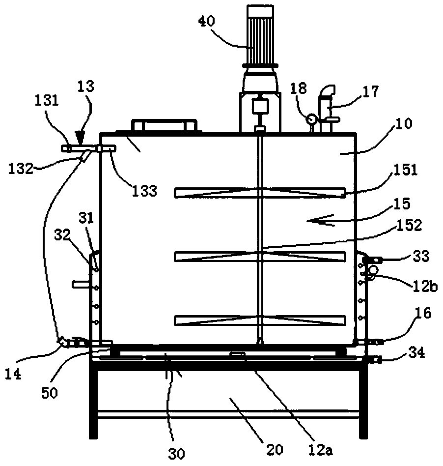
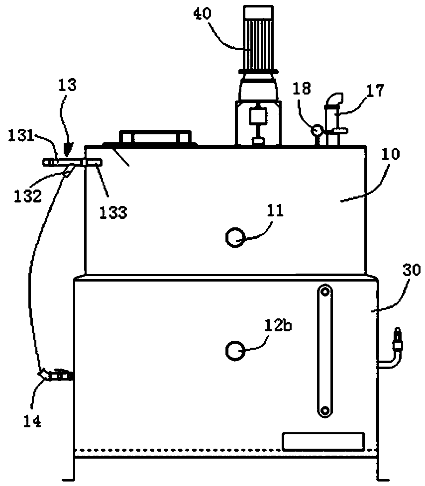
[0010] The present invention will be described in detail below in conjunction with the accompanying drawings.

[0011] A logarithmic fermenter with uniform heating, comprising a cylindrical fermenter body 10, a heating device 20 is provided at the bottom of the fermenter body 10, and a heat conduction tank with a heat transfer fluid is arranged between the heating device 20 and the bottom of the fermenter body 10 30. The heat conduction tank 30 extends from the bottom of the fermenter body 10 along the outer wall to the middle and upper part of the fermenter body 10. A heating rod 31 is provided in the cavity between the heat conduction tank 30 and the side wall of the fermenter body 10. The heating rod 31 is Ring along the side wall of the fermenter body 10; also includes an inner temperature detection device 11 arranged inside the fermenter body 10 and an outer temperature detection device one and two 12a, 12b arranged in the heat conduction tank 30, and an outer temperature ...


PUM


Abstract

The invention discloses a uniformly-heating logarithmic fermentation tank comprising a cylindrical fermentation tank body; a heating device is arranged at the bottom of the fermentation tank body; a heat conducting tank with a heat conducting liquid is arranged between the heating device and the bottom of the fermentation tank body; the heat conducting tank extends from the bottom of the fermentation tank body along the outer wall to the middle upper part of the fermentation tank body; a heating rod is arranged in a tank cavity between the heat conducting tank and the side wall of the fermentation tank body, and the heating rod has an annular shape along one circle of the side wall of the fermentation tank body. The fermentation tank also comprises an inner temperature detection device arranged inside the fermentation tank body, and a first outer temperature detection device and a second outer temperature detection device arranged in the heat conducting tank; the first outer temperature detection device is located in the tank cavity between the heat conducting tank and the bottom of the fermentation tank body, and the second outer temperature detection device is located in the tankcavity between the heat conducting tank and the side wall of the fermentation tank body. With the heating of the heating rod, stability of temperatures of the heat conducting liquid at various placesin the heating conducting tank is ensured, the stability of the fermentation temperature in the fermentation tank body is ensured, and the fermentation efficiency is improved.

Description

technical field [0001] The invention belongs to the technical field of fermentation tanks, in particular to a logarithmic fermentation tank with uniform heating. Background technique [0002] Microorganisms complete their life cycle in four extremes: spores, logarithmic division, maturity, and senescence. It takes a period of time for the spores to enter the logarithmic phase of division and proliferation during the growth process, and it must be driven by water. During the division and proliferation, the colonies will appear to reunite and enter the mature and aging sporulation period; the fermentation time needs to pass through N life cycle, the fermentation time cannot be shortened. [0003] The existing fermenter uses a heater to directly heat the fermenter, and the temperature detection device is installed inside the fermenter, so when the temperature in the fermenter reaches the preset temperature, the temperature of the barrel wall of the fermenter will be very high,...

Claims


Application Information

Patent Timeline
Patent Type & Authority Applications(China)
IPC IPC(8): C12M1/00C12M1/38C12M1/34C12M1/04C12M1/02
CPCC12M23/02C12M27/02C12M29/06C12M41/22
Inventor 林昱安
Owner 昆山千亿圆生物科技有限公司
Why Eureka
Try Eureka