Smart window and control method for smart window

A control method and smart window technology, applied in the field of smart windows, can solve problems that affect the user's health and discomfort, and achieve the effect of improving user experience and maintaining a clean environment

Active Publication Date: 2019-08-13
QINGDAO HAIER AIR CONDITIONER GENERAL CORP LTD +1
View PDF6 Cites 3 Cited by
  • Summary
  • Abstract
  • Description
  • Claims
  • Application Information

AI Technical Summary

Problems solved by technology

[0004] In order to solve the above problems in the prior art, that is, to solve the problem that when the indoor carbon dioxide concentration exceeds the user's suitable carbon dioxide concentration, it will make the user feel uncomfortable and even affect the user's health. The present invention provides a smart window. The smart window includes a body, a window assembly and a drive mechanism arranged on the body, the body is provided with an opening, the window assembly includes a glass layer structure, a filter layer structure and a power layer structure, and the drive mechanism respectively connected to the glass layer structure, the filter layer structure and the power layer structure, the driving mechanism is configured to be able to drive the glass layer structure, the filter layer structure and the power layer structure independently of each other, The smart window is set to be able to selectively make the glass layer structure, the filter layer structure and the power layer structure cover the to open

Method used


Image

  • Smart window and control method for smart window
  • Smart window and control method for smart window
  • Smart window and control method for smart window

Examples


Embodiment 1

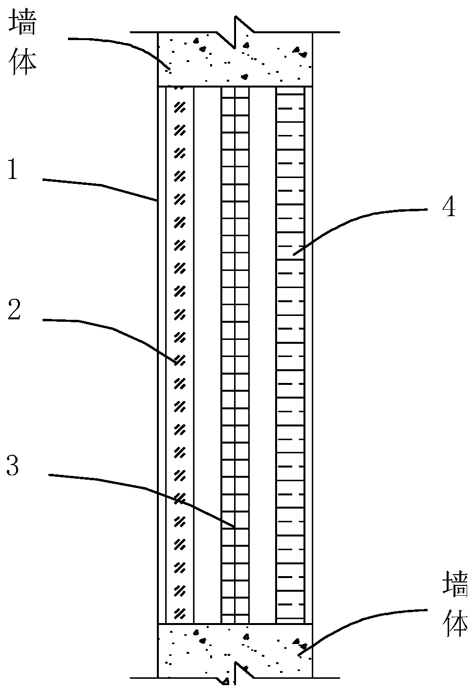
[0049] It should be noted that this embodiment takes the window assembly including the glass layer structure 2 , the filter layer structure 3 and the power layer structure 4 as an example to illustrate the technical solution of the control method of the present invention.

[0050] The control method of the present invention includes: obtaining the user's identity information; obtaining the indoor carbon dioxide concentration; obtaining the outdoor particle pollutant concentration; according to the user's identity information, indoor carbon dioxide concentration and outdoor particle pollutant concentration, selectively The glass layer structure 2 , the filter layer structure 3 and the dynamic layer structure 4 cover the opening 1 . In practical applications, according to the user's identity information, indoor carbon dioxide concentration and outdoor particle pollutant concentration, only the glass layer structure 2 can cover the opening 1, and only the power layer structure 4 c...

Embodiment 2

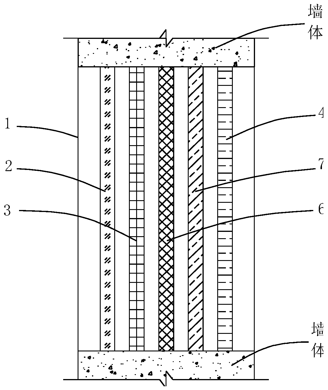
[0057] It should be noted that this embodiment illustrates the technical solution of the control method of the present invention by taking the window assembly including the glass layer structure 2 , the filter layer structure 3 , the power layer structure 4 , the heating layer structure 6 and the cooling layer structure 7 as an example.

[0058] Such as Figure 6 As shown, the control method of the present invention includes: obtaining the identity information of the user; obtaining the indoor carbon dioxide concentration; obtaining the outdoor particulate pollutant concentration; obtaining the indoor temperature; obtaining the outdoor temperature; If the concentration of carbon dioxide is set, and the concentration of outdoor particulate pollutants is greater than the preset value, then both the power layer structure 4 and the filter layer structure 3 cover the opening 1, and the power layer structure 4 is operated at a preset suction strength without making the glass The lay...

Embodiment 3

[0068] It should be noted that this embodiment takes the window assembly including glass layer structure 2, filter layer structure 3, power layer structure 4, heating layer structure 6, cooling layer structure 7 and humidification layer structure 8 as an example to illustrate the control of the present invention The technical scheme of the method.

[0069] The control method of the present invention includes: obtaining the identity information of the user; obtaining the indoor carbon dioxide concentration; obtaining the outdoor particle pollutant concentration; obtaining the indoor temperature; obtaining the outdoor temperature; obtaining the indoor humidity; obtaining the outdoor humidity; If the concentration of carbon dioxide in the air is greater than the preset indoor carbon dioxide concentration, and the concentration of outdoor particulate pollutants is greater than the preset value, then the power layer structure 4 and the filter layer structure 3 will cover the opening...


PUM


Abstract

The invention belongs to the technical field of smart equipment, and in particular, provides a smart window and a control method for the smart window. The smart window comprises a main body, a windowbody module and driving mechanisms; the main body is provided with an opening; the window body module comprises a glass layer structure, a filter layer structure and a power layer structure; the driving mechanisms can independently drive the glass layer structure, the filter layer structure and the power layer structure; and the smart window can selectively enable the glass layer structure, the filter layer structure and the power layer structure to cover an opening according to the identity information of users, indoor carbon dioxide concentration and outdoor particle pollutant concentration.When the indoor carbon dioxide concentration is higher than the carbon dioxide concentration (determined according to the identity information of the users) suitable for users, outdoor fresh air is absorbed indoors through the power layer structure to reduce the indoor carbon dioxide concentration, and the indoor air is filtered through the filter layer structure to prevent outdoor particle pollutants from entering indoors.

Description

technical field [0001] The invention belongs to the technical field of smart devices, and specifically provides a smart window and a control method for the smart window. Background technique [0002] The carbon dioxide concentration in the outdoor air is generally 350-450ppm, and the suitable indoor carbon dioxide concentration is generally 350-1000ppm. People of different ages or people with different physical conditions have different suitable carbon dioxide concentrations. People want to isolate noise and enjoy The comfort and convenience brought by the living space, if the indoor windows are closed for a long time, the indoor carbon dioxide concentration will be much higher than the outdoor average. When the indoor carbon dioxide concentration is higher than the suitable carbon dioxide concentration for people, the human body will feel uncomfortable, and even will affect people's health. [0003] Therefore, there is a need in the art for a smart window and a control met...

Claims


Application Information

Patent Timeline
Patent Type & Authority Applications(China)
IPC IPC(8): F24F7/013F24F3/16F24F13/28F24F11/64F24F11/72F24F13/00E06B5/00E06B7/28F24F110/70F24F110/64F24F120/10
CPCF24F7/013F24F13/28F24F11/64F24F11/72F24F13/00E06B5/00E06B7/28F24F2110/70F24F2110/64F24F2120/10F24F8/10
Inventor 于洋
Owner QINGDAO HAIER AIR CONDITIONER GENERAL CORP LTD
Why Eureka
Try Eureka