
An intelligent and dynamic monitoring system for mine grouting and its working method

A dynamic, grouting technology, applied in mining equipment, measuring devices, earth-moving drilling, etc., can solve the problems of long grouting time, poor grouting environment, complicated procedures, etc., to improve the supervision mechanism and prevent the waste of grouting. , The effect of saving slurry resources

Active Publication Date: 2020-12-04
新汶矿业集团有限责任公司孙村煤矿 +2
View PDF10 Cites 0 Cited by
  • Summary
  • Abstract
  • Description
  • Claims
  • Application Information

AI Technical Summary

Problems solved by technology

[0007] The purpose of the present invention is to solve the shortcomings in the prior art, such as: the existing grouting process adopts on-site grouting, the process is cumbersome, the equipment transfer time is long, the grouting time is long, the grout is seriously wasted, and the grouting environment is poor. During the grouting process, the grouting parameters (including flow rate and pressure) cannot be accurately collected, the grouting effect cannot be monitored quantitatively in real time, and the grouting bolts that do not meet the standard cannot be remedied in time. The existing grouting process lacks a supervision mechanism. quality is difficult to assure

Method used


Image

  • An intelligent and dynamic monitoring system for mine grouting and its working method
  • An intelligent and dynamic monitoring system for mine grouting and its working method
  • An intelligent and dynamic monitoring system for mine grouting and its working method

Examples


Embodiment Construction

[0027] The following will clearly and completely describe the technical solutions in the embodiments of the present invention with reference to the accompanying drawings in the embodiments of the present invention. Obviously, the described embodiments are only some, not all, embodiments of the present invention.

[0028] In describing the present invention, it should be understood that the terms "upper", "lower", "front", "rear", "left", "right", "top", "bottom", "inner", " The orientation or positional relationship indicated by "outside", etc. is based on the orientation or positional relationship shown in the drawings, and is only for the convenience of describing the present invention and simplifying the description, rather than indicating or implying that the referred device or element must have a specific orientation, so as to Specific orientation configurations and operations, therefore, are not to be construed as limitations on the invention.

[0029] refer to Figure ...


PUM


Abstract

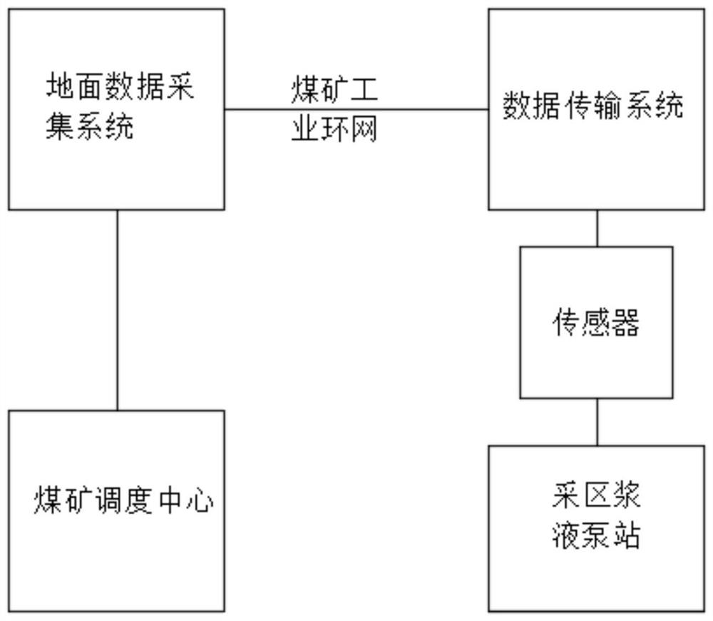
The invention discloses an intelligent and dynamic monitoring system for mine grouting and a working method thereof. The system comprises grouting pipes, a ball valve, a grout recovery pump, a high-precision intrinsic safety type pressure sensor, a high-precision intrinsic safety type flow sensor, a grouting anchor rod positioning system, a grouting anchor rod, a stirring device, a mining area grout pump station, a data transmission system, a ground data acquisition system and a coal mine dispatching center, wherein a plurality of grouting connectors are arranged on the periphery of the miningarea grout pump station, and the grouting pipes are arranged on the sides, deviating from the mining area grout pump station, of the grouting connectors separately. Through interaction of the ball valve, the high-precision intrinsic safety type pressure sensor, the high-precision intrinsic safety type flow sensor, the grouting anchor rod positioning system, the grouting anchor rod and a ground data acquisition system, grouting parameters are accurately collected in the grouting process, the grouting effect is detected in real time, and the grouting anchor rod which does not reach the standardcan be timely repaired.

Description

technical field [0001] The invention relates to the technical field of mine grouting, in particular to an intelligent and dynamic monitoring system for mine grouting. Background technique [0002] With the increasing mining depth, the pressure on the surrounding rock of the roadway is also increasing, especially the weak and broken roadway support is very difficult. Conventional support methods cannot effectively control the surrounding rock of the roadway, which affects the roadway. security and stability. The grouting bolt combines anchoring support technology and grouting reinforcement technology, which greatly improves the strength and self-supporting capacity of the surrounding rock, can effectively control the weak surrounding rock, and keep the roadway stable. The grouting amount and the grouting pressure of the grouting anchor will directly affect the grouting effect during the grouting process, so the grouting pressure and grouting flow rate of each grouting anchor...

Claims


Application Information

Patent Timeline
Patent Type & Authority Patents(China)
IPC IPC(8): E21D20/02E21F17/18G01D21/02
CPCE21D20/02E21F17/18G01D21/02
Inventor 辛恒奇王维张殿振李术才王琦吕长刚蒋振华颜磊郑兴博褚恒滨江贝曾昭楠周明庞继禄孙焕磊陈广友王帅王新稳张朋黄玉兵
Owner 新汶矿业集团有限责任公司孙村煤矿
Learn More