
Linear elastic model modeling solving method based on geometric spline

A model modeling and geometry technology, applied in the field of linear elastic model modeling and solving based on geometric splines, can solve problems such as large errors, time consumption, model representation errors in the modeling stage, etc.

Pending Publication Date: 2019-08-09
GUANGZHOU UNIVERSITY
View PDF0 Cites 3 Cited by
  • Summary
  • Abstract
  • Description
  • Claims
  • Application Information

AI Technical Summary

Problems solved by technology

[0002] The existing boundary element method often uses basis functions such as Lagrangian polynomials in the geometric modeling stage, and cannot accurately model a variety of analytical models commonly used in CAD / CAM (computer-aided manufacturing), such as the establishment of conic curve surfaces, circular For arc splines and trigonometric hyperbolic function curves and surfaces, it is easy to cause model representation errors in the modeling stage
On the other hand, in the existing methods, the basis function of the model representation in the geometric modeling stage is inconsistent with the shape function used in the simulation stage, resulting in repeated model conversions in the modeling and analysis process, resulting in large errors and more time-consuming

Method used


Image

  • Linear elastic model modeling solving method based on geometric spline
  • Linear elastic model modeling solving method based on geometric spline
  • Linear elastic model modeling solving method based on geometric spline

Examples


Embodiment 1

[0057] see figure 1 , one A linear elastic model modeling and solving method based on geometric splines, including:

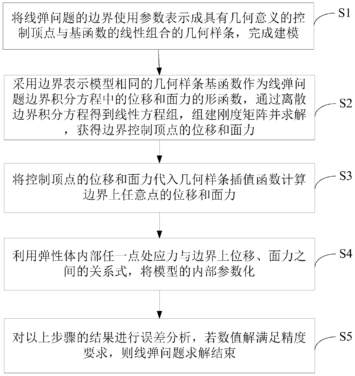
[0058] S1, using parameters to represent the boundary of the linear elastic problem as a geometric spline that is a linear combination of geometrically meaningful control vertices and basis functions to complete the modeling; in this embodiment, the boundary spline of the linear elastic problem is an arc spline . The arc spline is accurately represented by this geometric spline, figure 2 The chamfered trapezoidal boundary shown is an arc spline composed of a straight line segment and an arc segment. The quadratic geometric spline can be used to accurately model such a boundary, so that the arc spline can be transformed into a parameterized geometric sample. strips for application in the boundary element analysis process. The frequency sequence values ​​in the geometric spline representation of the boundary of this instance are: {0.8615,0.8615,0.8615, 0.1,...

Embodiment 2

[0081] see figure 1 , one A linear elastic model modeling and solving method based on geometric splines, including:

[0082] S1, using parameters to represent the boundary of the linear elastic problem as a geometric spline that is a linear combination of control vertices and basis functions with geometric meaning, to complete the modeling; in this embodiment, the boundary of the linear elastic problem is a mixture of trigonometric function curves inserted Boundary, the boundary spline of the linear elastic problem includes: cosine function curve and spline curve; Figure 7 As shown in the mixed boundary of the inserted trigonometric function curve, the cosine function curve can also be accurately modeled by the cubic (4th order) geometric spline adopted in the embodiment itself, and the remaining part itself is a geometric spline curve, so that the entire mixed boundary can be accurately modeled. Converted to geometric splines represented by parameters, which cannot be don...


PUM


Abstract

The invention discloses a geometric spline-based linear projectile model modeling solving method, which comprises the following steps of: expressing a boundary of a linear projectile problem as a geometric spline of a linear combination of a control vertex and a primary function with geometric significance by using parameters, and finishing modeling; taking a geometric spline primary function withthe same boundary representation model as a shape function of displacement and surface force in a boundary integral equation of the linear projectile problem, obtaining a linear equation set throughthe discrete boundary integral equation, building a stiffness matrix and solving to obtain the displacement and the surface force of a boundary control vertex; according to the method, the physical domain boundary of the 2D line projectile problem is modeled through the geometric spline, an accurate conversion method represented by a common model is provided, and the approximation error of the common boundary model in the modeling stage is avoided; a geometric spline basis function is adopted in a boundary integral equation to serve as a shape function for describing boundary physical quantity, and the model conversion time is saved.

Description

technical field [0001] The present invention relates to the technical field of computer-aided design and engineering, in particular to a linear elastic model modeling and solving method based on geometric splines. Background technique [0002] The existing boundary element method often uses basis functions such as Lagrangian polynomials in the geometric modeling stage, and cannot accurately model a variety of analytical models commonly used in CAD / CAM (computer-aided manufacturing). When using arc splines and trigonometric hyperbolic function curves and surfaces, it is easy to cause model representation errors in the modeling stage. On the other hand, in the existing methods, the basis function of the model representation in the geometric modeling stage is inconsistent with the shape function used in the simulation stage, resulting in repeated model conversions in the modeling and analysis process, which brings large errors and consumes more time. . Contents of the invent...

Claims


Application Information

Patent Timeline
IPC IPC(8): G06F17/50G06Q50/08
CPCG06Q50/08G06F30/13G06F30/17G06F30/23
Inventor 方美娥李想唐静
Owner GUANGZHOU UNIVERSITY
Learn More