
Simulated circuit fault testing method based on sequential testing

A technology for simulating circuit faults and testing methods, applied in the direction of measuring electricity, measuring electrical variables, measuring devices, etc., can solve problems such as affecting the efficiency of the fault identification process, ignoring the difference of effective information, and lack of flexibility in the modeling process.

Active Publication Date: 2019-08-09
UNIV OF ELECTRONICS SCI & TECH OF CHINA
View PDF10 Cites 3 Cited by
  • Summary
  • Abstract
  • Description
  • Claims
  • Application Information

AI Technical Summary

Problems solved by technology

However, the existing fault diagnosis methods based on machine learning are all directly modeled through all the collected measuring point information, focusing on the recognition accuracy of the model as a whole, while ignoring the differences in the effective information of each fault in the recognition process , thus affecting the efficiency of the fault identification process, and the modeling process lacks flexibility

Method used


Image

  • Simulated circuit fault testing method based on sequential testing
  • Simulated circuit fault testing method based on sequential testing
  • Simulated circuit fault testing method based on sequential testing

Examples


Embodiment

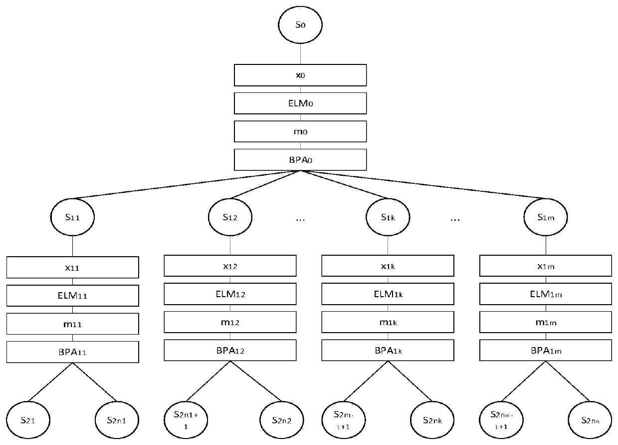
[0061] figure 1 It is a flowchart of an analog circuit fault testing method based on sequential testing in the present invention.

[0062] In this example, if figure 1 Shown, a kind of analog circuit failure testing method based on sequential test of the present invention comprises the following steps:

[0063] S1: Acquisition of voltage values ​​at different corner frequencies

[0064] Collect the voltage eigenvalues ​​of N groups of samples at different corner frequencies in the fault state and healthy state of the analog circuit, denoted as X={x 1 ,x 2 ,...,x N}, where the voltage eigenvalue xi={x i,1 ,x i,2 ,...,x i,k ,...,x i,T},x i,k is the voltage characteristic value of the i-th sample collected at the k-th corner frequency, and T is the number of corner frequencies;

[0065] Construct the expected output vector Y={y of each sample 1 ,y 2 ,...,y i ,...,y N}, where y i ={y i,1 ,y i,2 ,y i,3 ,...y i,j ,...,y i,M}, M is the total number of fault states...

example

[0111] In order to illustrate the technical effects of the present invention, an analog circuit is taken as an example to verify the implementation of the present invention. Such as image 3 As shown, the circuit is composed of 4 second-order filters and an adder, and it is modeled and simulated using Pspice software. The tolerance of R1, R2, R3, R4, R5, R6, R7 and R8 is ±10%, the tolerance of C1, C2, C3, C4, C5, C6, C7 and C8 is ±5%, the gain of the amplifier is Av1 , the tolerance of Av2, Av3 and Av4 is ±1%, and the tolerance of R9, R10 and R11 is ±1%. Analysis shows that the circuit has 4 corner frequencies: 10Hz, 100Hz, 10kHz and 100kHz. The probability of a single fault in an analog circuit accounts for about 80%, so only the state monitoring and health management of a single fault is considered.

[0112] Set Av 1 ,Av 2 ,Av 3 and Av 4 In (1.1~1.5%)Xn, (1.6~2%)Xn, (2.1~2.5%)Xn, (2.6~3.0%)Xn, (3.1~3.5%)Xn, (3.6~4.0%)Xn, ( 4.1~4.5%)Xn, (4.6~5.0%)Xn, (5.1~5.5%)Xn, (5....


PUM


Abstract

The invention discloses a simulated circuit fault testing method based on sequential testing. Effectiveness of measuring points is estimated through a conditional entropy, the characteristic value ofthe measuring points with high fault identifying ability is selected to serve as information of an input layer of an extreme learning machine, and the evidence vector for expressing the fault state identifying result is generated; and then a belief function is generated based on a D-S theory, according to affinity propagation, a fault state set is separated into a plurality of fault subsets, and diagnostic models of the fault subsets are further generated until the fault state is completely separated or separated to be in the optimal state. The simulated circuit fault testing method has the characteristics of high fault identification precision, high fault identification efficiency and the like.

Description

technical field [0001] The invention belongs to the technical field of circuit fault diagnosis and machine learning, and more specifically relates to a sequential testing-based analog circuit fault testing method. Background technique [0002] With the increasing integration of analog circuits, the state monitoring of complex circuits has become an important issue in the field of electronic system research. How to effectively monitor the fault status of analog circuit systems has become one of the research hotspots in this field. Existing analog circuit fault state identification methods are mainly divided into two types of fault diagnosis methods based on empirical knowledge and based on data drive. [0003] The fault diagnosis method based on empirical knowledge abstracts the dependencies between test points and each fault mode through the mechanism model relationship obtained from the circuit, and then generates an efficient test strategy for locating faults, mainly incl...

Claims


Application Information

Patent Timeline
IPC IPC(8): G01R31/3163
CPCG01R31/3163
Inventor 刘震梅文娟杜立杨成林周秀云
Owner UNIV OF ELECTRONICS SCI & TECH OF CHINA
Learn More