
Optical-based on-line detection device

A detection device and optical technology, applied in the field of detection, can solve the problems of long maintenance cycle, inability to adjust and control in time, and high maintenance cost, and achieve the effect of avoiding influence, improving detection efficiency and detection quality.

Pending Publication Date: 2019-08-09
HEFEI GOLD STAR MECHATRONICS TECH DEV CO LTD
View PDF1 Cites 0 Cited by
  • Summary
  • Abstract
  • Description
  • Claims
  • Application Information

AI Technical Summary

Problems solved by technology

The fluorescence analysis method has a history of more than 40 years in the quality control of cement, but it needs to take samples to the laboratory for analysis and calculation during the cement production process, which is a hysteresis analysis and cannot be adjusted in time; although the neutron activation method belongs to a control technology, but there is a potential safety hazard of radiation sources, and the maintenance period is long and the maintenance cost is high

Method used


Image

  • Optical-based on-line detection device
  • Optical-based on-line detection device
  • Optical-based on-line detection device

Examples


Embodiment Construction

[0015] The specific implementation manner of the present invention will be further described in detail below by describing the embodiments in conjunction with the accompanying drawings.

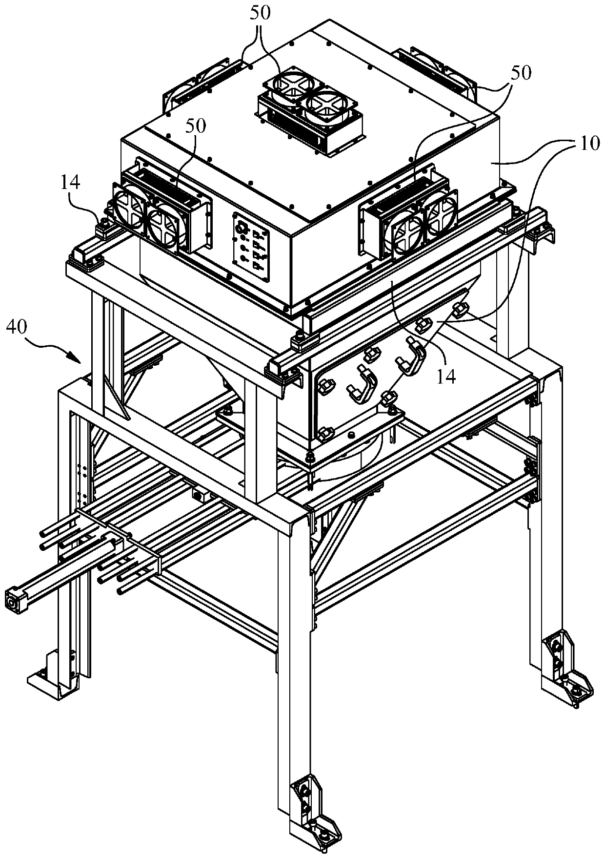
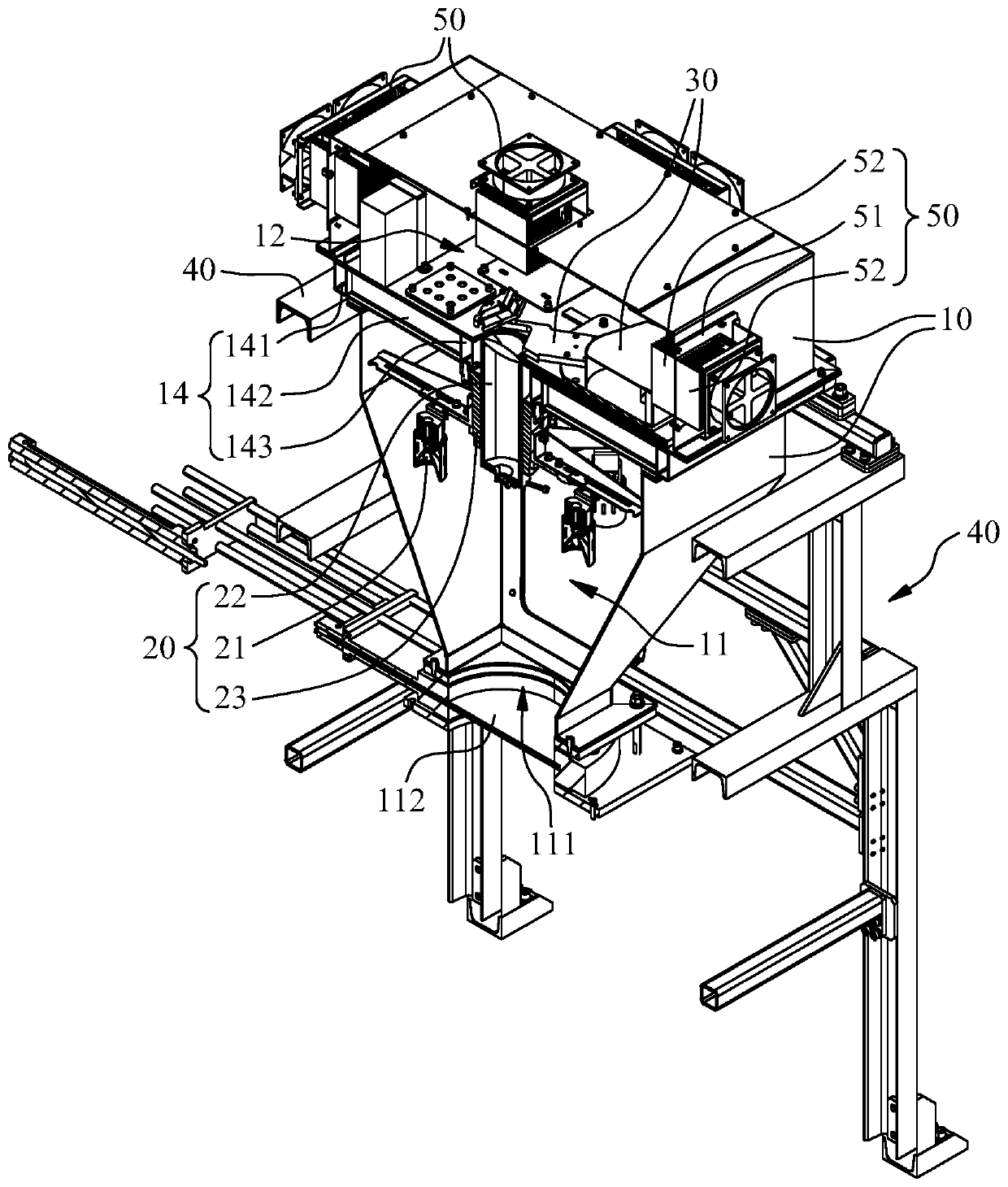
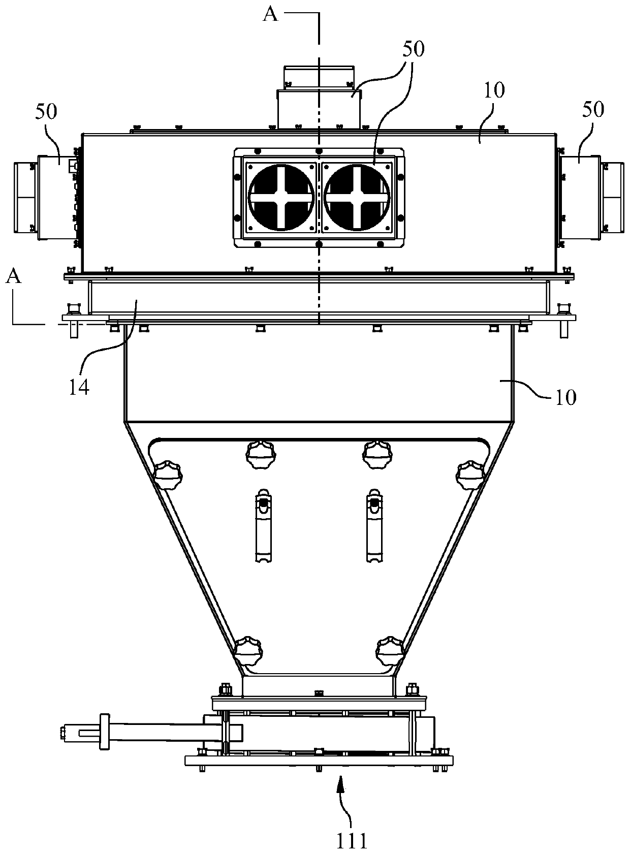
[0016] An optical-based on-line detection device, including a light collection component 20 and an analysis component 30 installed in a casing 10, the casing 10 encloses a chamber 11 and a chamber 2 12 that are isolated from each other, and the chambers 1 and 2 The isolation walls of 11 and 12 are provided with an optical path 13a for the light to be measured to pass through.

[0017] The light collection component 20 is installed in the chamber one 11, and the wall of the chamber one 11 adjacent to the conveyor belt A is provided with a light inlet 111, and the opening of the light inlet 111 is provided with a shutter 112, and the shutter 112 is in the closed position When the gate plate 112 is in the open position, the opening of the light entrance hole 111 is opened. In this way, opening ...


PUM


Abstract

The present invention belongs to the technical field of detection, and particularly relates to an optical-based on-line detecting device. The detecting device comprises a light collecting component and an analysis component that are installed in a casing. The casing enclosure forms a mutually isolated chamber 1 and chamber 2, and an isolation wall body between the chamber 1 and the chamber 2 is provided with an optical path for to-be-detected light to pass; the light collecting component is arranged inside the chamber 1, the wall of the chamber 1 adjacent to the to-be-detected material is opened with an optical hole, and the hole mouth of the optical hole is provided with a gate plate; and the analysis component is arranged inside the closed chamber 2. According to the optical-based on-line detecting device provided by the present invention, the light collecting component and the analysis component are separately arranged in two mutually isolated chambers, and the optical path is set for the to-be-detected light to pass from the chamber 2 to the completely closed chamber 1, so that the influence of the dust particles on the detection result can be effectively avoided, and the detection efficiency and detection quality of the detecting device in the harsh environment of high dust can be greatly improved.

Description

technical field [0001] The invention belongs to the technical field of detection, in particular to an optical-based on-line detection device. Background technique [0002] Cement is an important basic raw material in the national economy and is widely used in construction, road, water conservancy, marine and national defense projects. Cement quality control is a very important part of the cement production process, which directly affects product quality, and the use of unqualified cement will cause great safety hazards in construction projects. The existing cement quality testing methods include the mature fluorescence analysis method and the new neutron activation method in recent years. The fluorescence analysis method has a history of more than 40 years in the quality control of cement, but it needs to take samples to the laboratory for analysis and calculation during the cement production process. Control technology, but there is a potential safety hazard of radiation ...

Claims


Application Information

Patent Timeline
IPC IPC(8): G01N21/01
CPCG01N21/01
Inventor 徐勇刘世胜袁学义
Owner HEFEI GOLD STAR MECHATRONICS TECH DEV CO LTD
Learn More