Rotor of rotating electrical machine

A technology for rotating electrical machines and rotors, which is applied in the field of rotors, and can solve problems such as end plate 105, rotor shaft 101 offset, etc.

Inactive Publication Date: 2019-08-06
HONDA MOTOR CO LTD
View PDF7 Cites 0 Cited by
  • Summary
  • Abstract
  • Description
  • Claims
  • Application Information

AI Technical Summary

Problems solved by technology

like Image 6 As shown, in the rotor 100A, a plurality of electromagnetic steel sheets 103 are fixed to each other with an adhesive. Therefore, even if an attempt is made to sandwich the end plate 105 between the flange portion 102 and the rotor yoke 104, the elastic force generated by the electromagnetic steel sheets 103, that is, the end plate 105 presses against the flange portion 102 will also be weak, which may cause the phase of the end plate 105 to shift relative to the rotor shaft 101

Method used


Image

  • Rotor of rotating electrical machine
  • Rotor of rotating electrical machine
  • Rotor of rotating electrical machine

Examples


Embodiment Construction

[0044] Below, refer to Figures 1 to 4B , the rotor of the rotating electric machine according to one embodiment of the present invention will be described.

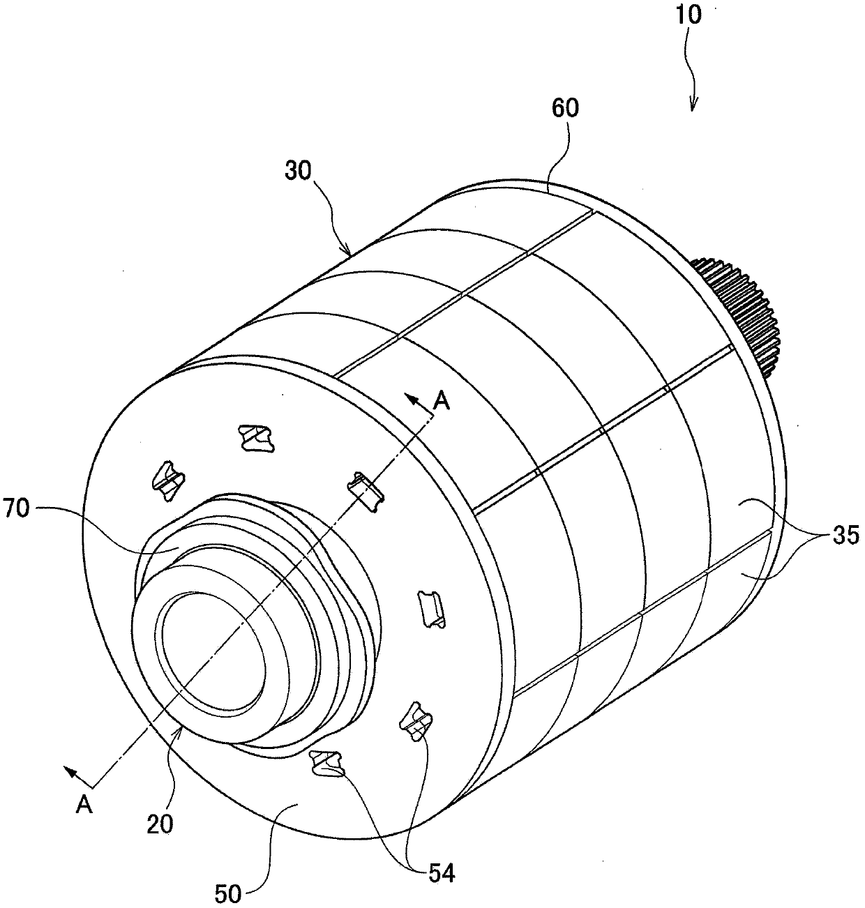
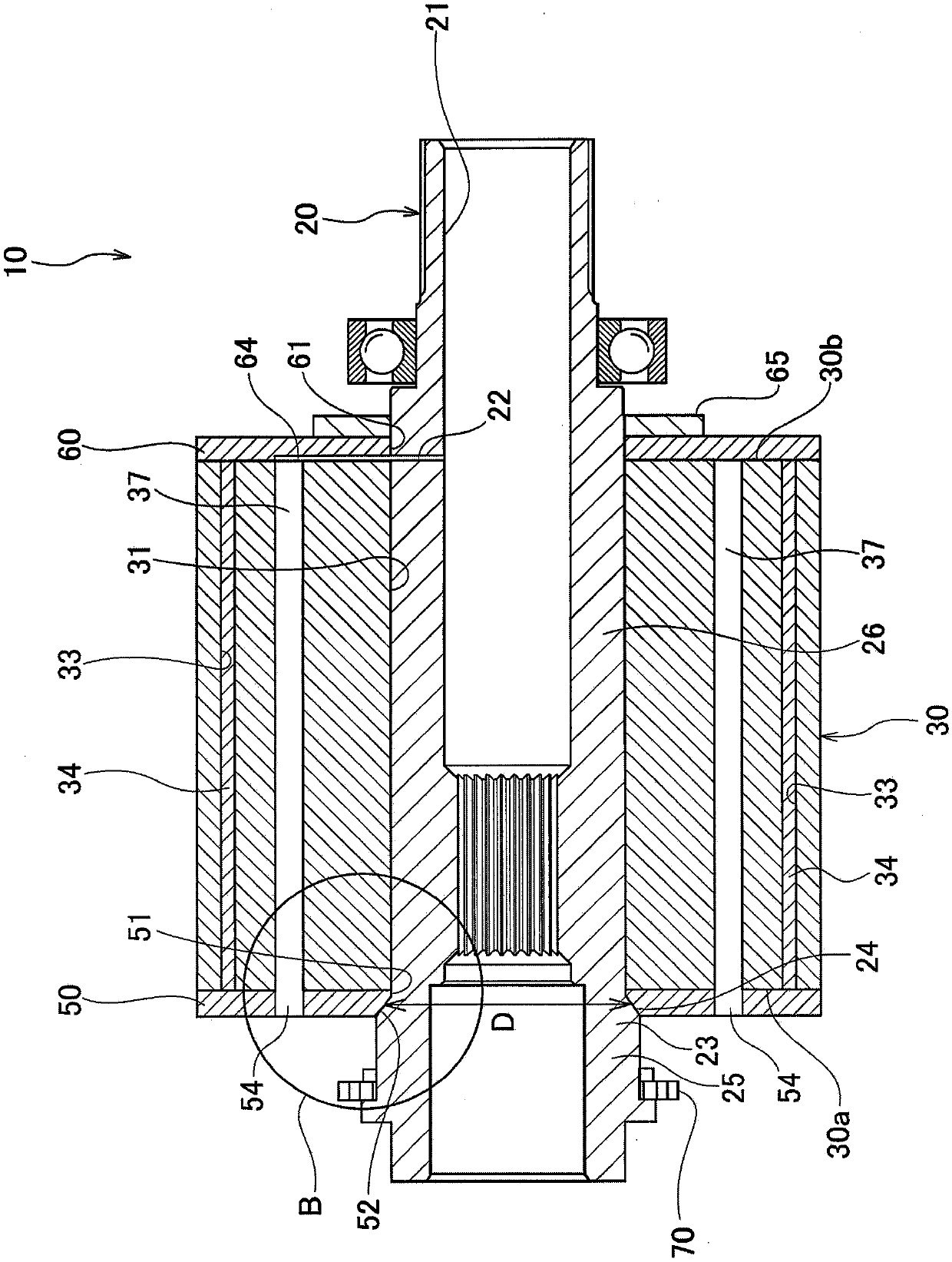
[0045] Such as figure 1 and figure 2 As shown, the rotor 10 of the rotating electric machine according to this embodiment includes: a rotor shaft 20; a rotor yoke 30 press-fitted into the outer peripheral portion of the rotor shaft 20; side; the second end plate 60 is disposed on the other axial side of the rotor yoke 30 ; and the resolver 70 detects the rotation angle of the rotor 10 .

[0046] In the rotor shaft 20 , a cooling flow path 21 through which the refrigerant flows is formed inside. The cooling flow path 21 extends in the axial direction inside the rotor shaft 20 and is configured to be capable of supplying a refrigerant from the outside. As the refrigerant, for example, ATF (Automatic Transmission Fluid) is used, and a supply path is formed so that ATF circulates between the transmission case and the m...


PUM


Abstract

An object of the present invention is to provide a rotor of a rotating electrical machine capable of effectively preventing relative rotation of an end plate with respect to a rotor shaft while reducing the press-in load of a rotor yoke. A rotor (10) for a rotating electrical machine is provided with a rotor shaft (20), a rotor yoke (30), and first and second end plates (50, 60). The first end plate (50) is disposed between a plate fixing part (23) provided on the rotor shaft (20) and one end surface (30a) in the axial direction of the rotor yoke (30). The plate fixing part (23) is provided with an inclined surface (24); the inclined surface is inclined so that the outer diameter (D) becomes larger as the inclined surface is away from the end surface (30a) of the rotor yoke (30) in the press-fitting direction of the rotor yoke (30). The inner peripheral surface of the shaft insertion hole (51) of the first end plate (50) has an inner peripheral inclined surface (52) that is in contactwith the inclined surface (24) of the plate fixing part (23).

Description

technical field [0001] The present invention relates to a rotor mounted in a rotating electrical machine such as an electric vehicle. Background technique [0002] Conventionally, a rotating electrical machine including a stator and a rotor is known (for example, Patent Document 1). [0003] Such as Figure 5A and Figure 5B As shown, a rotor 100 of a general rotating electrical machine includes: a rotor shaft 101 having a flange portion 102 on one end side in the axial direction; a rotor yoke 104 in which a plurality of electromagnetic steel sheets 103 are laminated and pressed into the rotor shaft 101; and an end plate Numeral 105 is provided at one axial end of the rotor yoke 104 and holds a magnet (not shown) accommodated in the rotor yoke 104 . In addition to the function of preventing the magnets from popping out, the end plate 105 may also be used as a shaft center cooling oil passage, and it is necessary to prevent relative rotation (phase shift) between the rotor ...

Claims


Application Information

Patent Timeline
IPC IPC(8): H02K1/27
CPCH02K1/276H02K7/003H02K1/32H02K5/15H02K1/22
Inventor 大平健悟
Owner HONDA MOTOR CO LTD
Why Eureka
Try Eureka