
Microphone multi-band clock frequency response detection equipment

A technology for testing equipment and microphones, applied to electrical components and other directions, can solve the problems of large detection misjudgments, lower quality standards, and low work efficiency, and achieve the effect of solving large misjudgments, improving accuracy, and ensuring consistency

Active Publication Date: 2021-09-28
GREEN TECH SOLUTION CO LTD
View PDF10 Cites 0 Cited by
  • Summary
  • Abstract
  • Description
  • Claims
  • Application Information

AI Technical Summary

Problems solved by technology

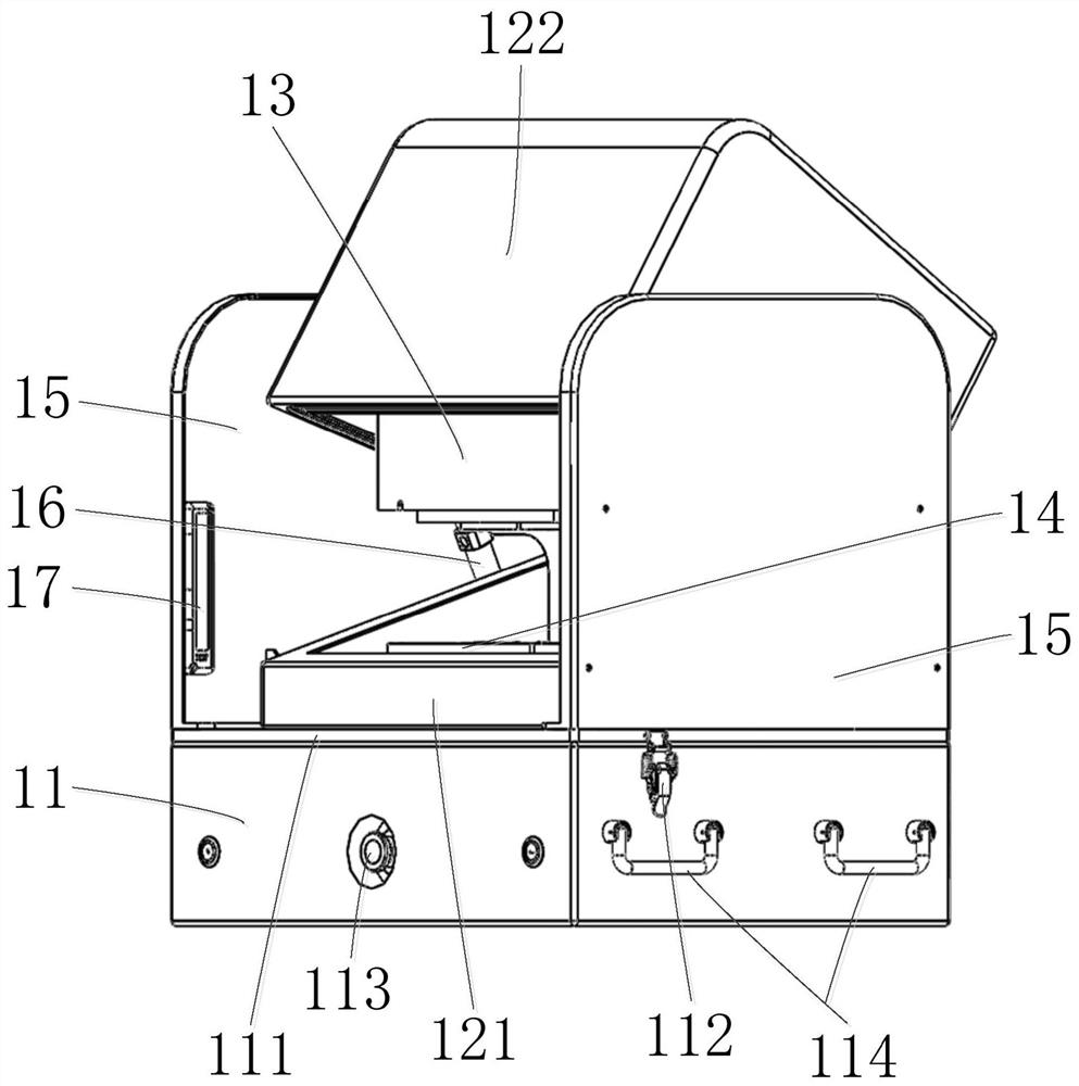
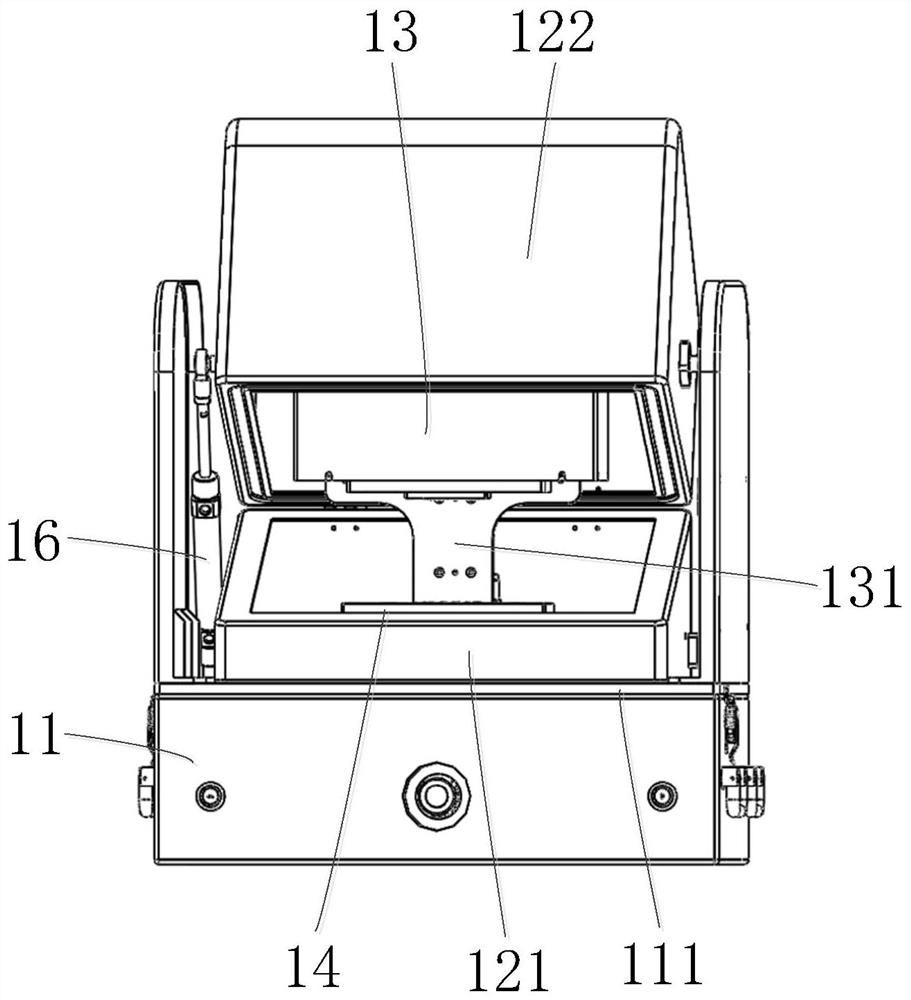
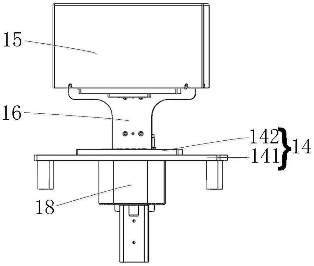
[0004] The invention provides a microphone multi-band clock frequency response detection device, which sets the test terminal on the test platform, and presses down the pressing part so that the electrical terminal of the microphone module to be tested is electrically connected with the test terminal, and at the same time emits a signal through the sounder. Sounds of different frequencies, and then the controller compares the sound data received by the microphone module to be tested and the standard microphone, and then judges the yield rate of the microphone module to be tested, so as to solve the problem that the microphone is manually detected in the prior art and the detection method is simple. Whether there is any abnormality in the microphone line, the work efficiency is low and the detection misjudgment is large. Even many companies only conduct random inspections on the products due to the large production volume of the products. It is easy to cause defective products to flow into the market, resulting in a decline in quality. The problem of poor user experience

Method used


Image

  • Microphone multi-band clock frequency response detection equipment
  • Microphone multi-band clock frequency response detection equipment
  • Microphone multi-band clock frequency response detection equipment

Examples


Embodiment Construction

[0034] The following will clearly and completely describe the technical solutions in the embodiments of the present invention with reference to the accompanying drawings in the embodiments of the present invention. Obviously, the described embodiments are only some, not all, embodiments of the present invention. Based on the embodiments of the present invention, all other embodiments obtained by those skilled in the art without making creative efforts belong to the protection scope of the present invention.

[0035] Directional terms mentioned in the present invention, such as "up", "down", "front", "back", "left", "right", "inside", "outside", "side", "top" Words such as "bottom" and "bottom" only refer to the orientation of the drawings, and the directional terms used are used to illustrate and understand the present invention, but not to limit the present invention.

[0036] Words such as "first" and "second" in the terminology of the present invention are only used for des...


PUM


Abstract

The invention provides a microphone multi-band clock frequency response detection device, which includes a controller, a base box, a fixed shell, a test platform, a pressing part, a standard microphone, a sounder and a shielding box cover, and the fixed shell is arranged on the base In the seat box, the test platform is connected to the base box, and there are test terminals and through holes on the test platform, and the pressing part is movable above the test platform, which is used to squeeze the electrical terminals and electrically connect the test terminals. A standard microphone and sounder are housed in the fixed housing. The microphone multi-band clock frequency response detection device of the present invention sets the test terminal on the test platform, presses down the pressing part so that the electrical terminal of the microphone module to be tested is electrically connected to the test terminal, and at the same time emits sounds of different frequencies through the sounder , and then the controller compares the sound data received by the microphone module under test with the standard microphone, and then judges the yield rate of the microphone module under test.

Description

technical field [0001] The invention relates to the field of microphone frequency response detection equipment, in particular to a microphone multi-band clock frequency response detection equipment. Background technique [0002] Microphone is a very common electronic product for sound recording. With the continuous improvement of user requirements, microphone products continue to develop in the direction of integrated modularization and thinning, which also leads to smaller and smaller spaces in electronic products. At the same time It also causes the sound recorded by the microphone to be abnormal, and the sound produced by the corresponding sound device is often accompanied by noise, and it occurs in different clock frequency bands. However, most companies in the prior art only conduct simple manual detection of the microphone, and the detection method is simply to test whether the microphone line is abnormal, the work efficiency is low and the detection misjudgment is lar...

Claims


Application Information

Patent Timeline
Patent Type & Authority Patents(China)
IPC IPC(8): H04R29/00
CPCH04R29/001
Inventor 曹波赵江玲于开峰周辉
Owner GREEN TECH SOLUTION CO LTD
Learn More