Fighting training equipment
A technology of fighting training and training equipment, which is applied in the field of fighting training equipment, and can solve problems such as inability to train users' response ability
- Summary
- Abstract
- Description
- Claims
- Application Information
AI Technical Summary
Problems solved by technology
Method used
Image

Examples
Embodiment 1
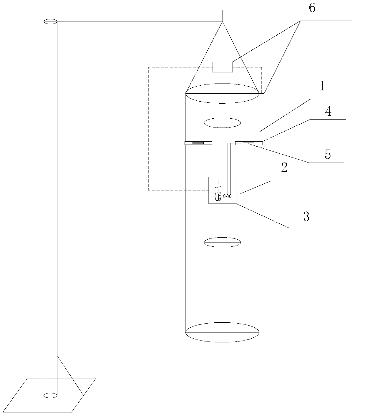
[0088] see figure 1 , figure 1 It is a schematic structural diagram of a boxing training device provided in Embodiment 1 of the present application.
[0089] Such as figure 1 As shown, the boxing training equipment provided in this embodiment includes:
[0090] Training equipment body 1;
[0091] an inner tank 2 fixed inside the body of the training equipment;
[0092] At least one retractable arm 4 disposed in the inner container, the arm is provided with a pop-up device 5;
[0093] An ejection channel that matches the arms one by one is set between the inner bag and the training equipment body, so that the arm can be ejected from the inner bag through the ejection channel under the action of the ejectable device. extends outside the training device body;
[0094] The arm control assembly 6 arranged on the training equipment body;
[0095] a driving device 3 connected to the ejectable device;
[0096] The arm control assembly is connected to the driving device and is ...
Embodiment 2
[0153] In this embodiment, an arm is used as an example to illustrate the boxing training equipment.
[0154] This embodiment provides another second extension direction changing device which is different from the first embodiment and can change the direction in which the arm is extended.
[0155] see Figure 8 , Figure 8 It is a schematic structural diagram of a first extension direction changing device provided in Embodiment 2 of the present application.
[0156] Such as Figure 8 As shown, the second stretching direction changing device includes: a first elastic pull wire 1001, a second elastic pull wire 1002, a second push rod 1003, a third push rod 1004, a second electromagnet 1005, a third electromagnet 1006, The second magnetic metal sheet 1011, the third magnetic metal sheet 1012, the third guide wheel 1007, the fourth guide wheel 1008, the fifth guide wheel 1009 and the sixth guide wheel 1010; the second electromagnet and the third electromagnetic The irons are r...
Embodiment 3
[0169] In this embodiment, three arms are taken as an example to illustrate the fighting training equipment.
[0170] Its setting location is as Figure 9 As shown, the structure contained therein can refer to Embodiment 1 and Embodiment 2, and will not be repeated here.
[0171] In the above embodiment, the first ejector pin, the second ejector pin and the third ejector pin involved are all ejector pins with the same structure. The specific structure of the ejector pin will be described below by taking the first ejector pin as an example.
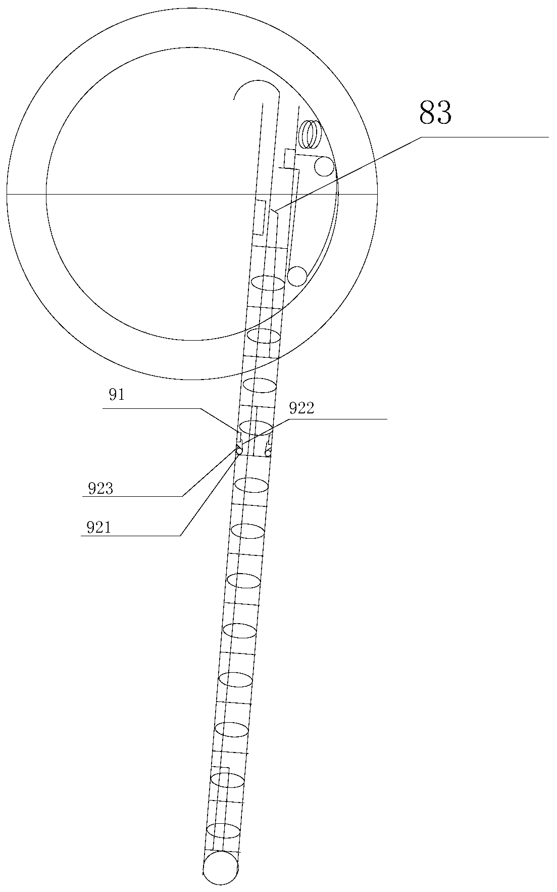
[0172] Such as Figure 10 As shown, the first push rod 83 is a bendable elastic member, such as a shrapnel, and one end of the first push rod is provided with a bent part, which is used to resist the first magnetic metal sheet 85. When the arm is retracted, the first push rod Rod 83 will move upwards (with Figure 10 Based on the position state), the bending part will push the first magnetic metal sheet to move upwards until it touches th...
PUM
 Abstract
Description
Claims
Application Information
 - R&D
- Intellectual Property
- Life Sciences
- Materials
- Tech Scout
- Unparalleled Data Quality
- Higher Quality Content
- 60% Fewer Hallucinations
Browse by: Latest US Patents, China's latest patents, Technical Efficacy Thesaurus, Application Domain, Technology Topic, Popular Technical Reports.
© 2025 PatSnap. All rights reserved.Legal|Privacy policy|Modern Slavery Act Transparency Statement|Sitemap|About US| Contact US: help@patsnap.com