An automatic framing system
A framing and automatic technology, applied in the direction of packaging, transportation and packaging, single objects, etc., can solve the problems of low framing efficiency, collision and scratching of aluminum rods and pipes, unstable transportation and framing, etc.
- Summary
- Abstract
- Description
- Claims
- Application Information
AI Technical Summary
Problems solved by technology
Method used
Image
Examples
Embodiment 1
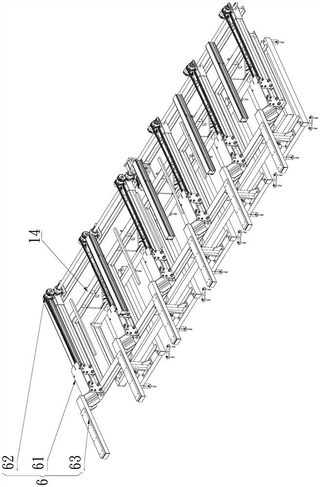
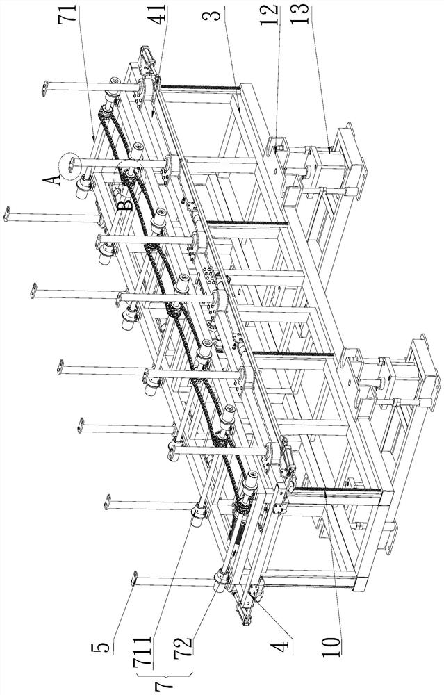
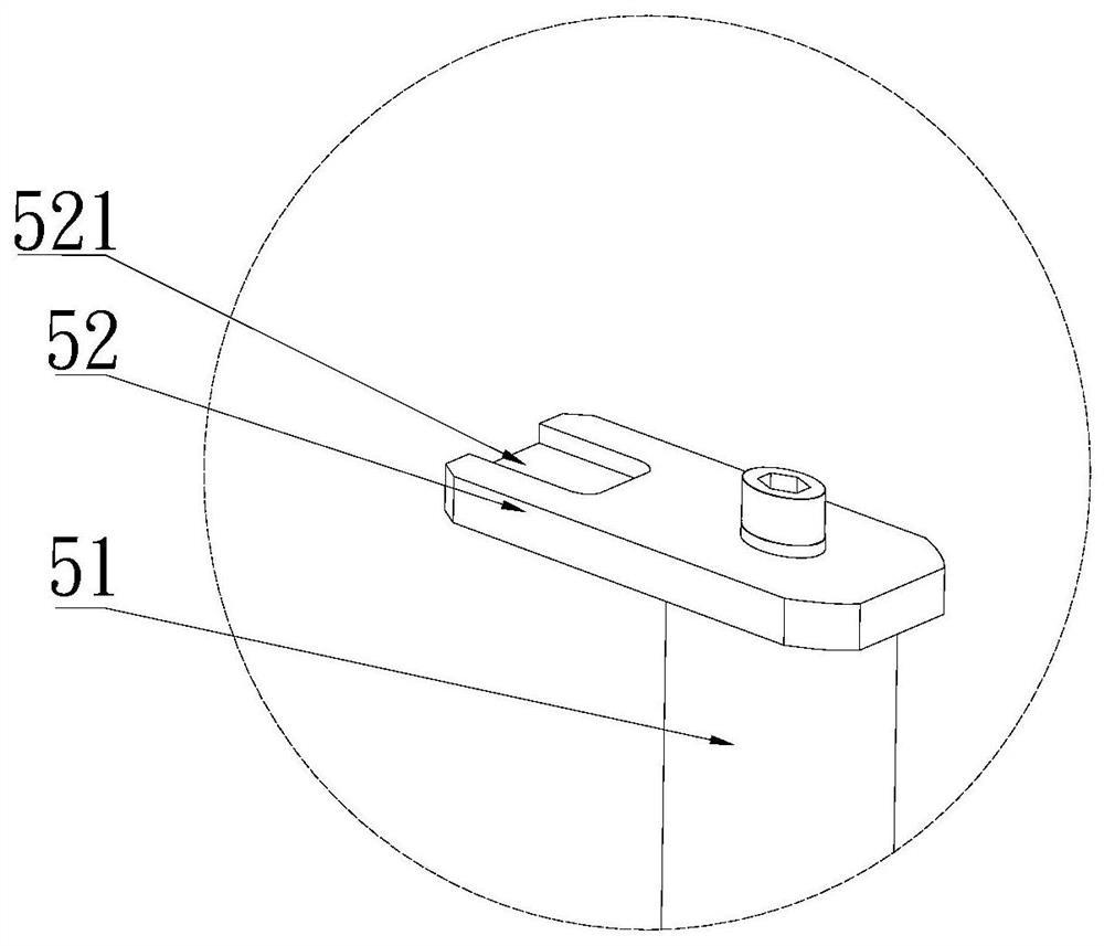
[0037] like Figure 1-9 The shown automatic frame loading system includes a material lifting device 1, a material loading device 2 and a material frame conveying device arranged in sequence along the material feeding direction; the material lifting device 1 includes a first frame 14; the second A frame 14 is provided with several supporting mechanisms 6 that can go back and forth above the charging device 2; the charging device 2 includes a second frame 3; The lifting mechanism 4 for lifting the second frame 3 and the material frame for loading materials; the lifting mechanism 4 includes a support frame 41 slidingly sleeved on the second frame 3; The spacer of the material; the support frame 41 is provided with several pairs of support assemblies 5 for bridging the spacer; The conveying assembly 7 of the frame conveying device; the material frame is placed on the conveying assembly 7 .
[0038] Among them, because the length of the material is long, in order to ensure that t...
Embodiment 2
[0048] like Figure 1-9 The shown automatic frame loading system includes a material lifting device 1, a material loading device 2 and a material frame conveying device arranged in sequence along the material feeding direction; the material lifting device 1 includes a first frame 14; the second A frame 14 is provided with several supporting mechanisms 6 that can go back and forth above the charging device 2; the charging device 2 includes a second frame 3; The lifting mechanism 4 for lifting the second frame 3 and the material frame for loading materials; the lifting mechanism 4 includes a support frame 41 slidingly sleeved on the second frame 3; The spacer of the material; the support frame 41 is provided with several pairs of support assemblies 5 for bridging the spacer; The conveying assembly 7 of the frame conveying device; the material frame is placed on the conveying assembly 7; wherein the outer contour of the support frame is located in a rectangular frame; the outer ...
Embodiment 3
[0059] like Figure 1-9 The shown automatic frame loading system includes a material lifting device 1, a material loading device 2 and a material frame conveying device arranged in sequence along the material feeding direction; the material lifting device 1 includes a first frame 14; the second A frame 14 is provided with several supporting mechanisms 6 that can go back and forth above the charging device 2; the charging device 2 includes a second frame 3; The lifting mechanism 4 for lifting the second frame 3 and the material frame for loading materials; the lifting mechanism 4 includes a support frame 41 slidingly sleeved on the second frame 3; The spacer of the material; the support frame 41 is provided with several pairs of support assemblies 5 for bridging the spacer; The conveying assembly 7 of the frame conveying device; the material frame is placed on the conveying assembly 7; wherein the outer contour of the support frame is located in a rectangular frame; the outer ...
PUM
 Abstract
Description
Claims
Application Information
 - Generate Ideas
- Intellectual Property
- Life Sciences
- Materials
- Tech Scout
- Unparalleled Data Quality
- Higher Quality Content
- 60% Fewer Hallucinations
Browse by: Latest US Patents, China's latest patents, Technical Efficacy Thesaurus, Application Domain, Technology Topic, Popular Technical Reports.
© 2025 PatSnap. All rights reserved.Legal|Privacy policy|Modern Slavery Act Transparency Statement|Sitemap|About US| Contact US: help@patsnap.com


