
Robot part processing clamp with multi-angle fixing function

A fixed function, robot technology, applied in the application of jigs for robot parts processing, and the field of jigs for robot parts processing, can solve the problem that the movement of robot parts is not stable and reliable, and only one robot part can be clamped at the same time. The angle is not convenient, fast, and accurate enough to achieve the effect of being moved and adjusted to be stable and reliable, fast in efficiency, and easy to organize

Inactive Publication Date: 2019-07-30
XUZHOU COLLEGE OF INDAL TECH
View PDF8 Cites 6 Cited by
  • Summary
  • Abstract
  • Description
  • Claims
  • Application Information

AI Technical Summary

Problems solved by technology

[0004] The purpose of the present invention is to solve the problem that the existing jig for robot parts processing is not convenient, fast, and accurate enough to adjust the position and angle of the robot parts to be processed after the robot parts are clamped and fixed, and the jig can adjust the robot parts. The range of position and angle of parts processing is small, the fixture is not stable and reliable when driving robot parts, and the fixture can only grip one robot part at the same time for processing, and the efficiency of the fixture when gripping robot parts for processing is slow. And after the robot parts are processed, the jig cannot quickly move the robot parts to the designated point for processing, and the diversity of the jig work is poor. A jig for robot parts processing with a multi-angle fixing function is proposed

Method used


Image

  • Robot part processing clamp with multi-angle fixing function
  • Robot part processing clamp with multi-angle fixing function
  • Robot part processing clamp with multi-angle fixing function

Examples


Embodiment Construction

[0048] The technical solutions of the present invention will be clearly and completely described below in conjunction with the embodiments. Apparently, the described embodiments are only some of the embodiments of the present invention, not all of them. Based on the embodiments of the present invention, all other embodiments obtained by persons of ordinary skill in the art without creative efforts fall within the protection scope of the present invention.

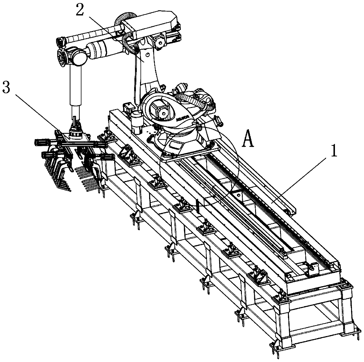
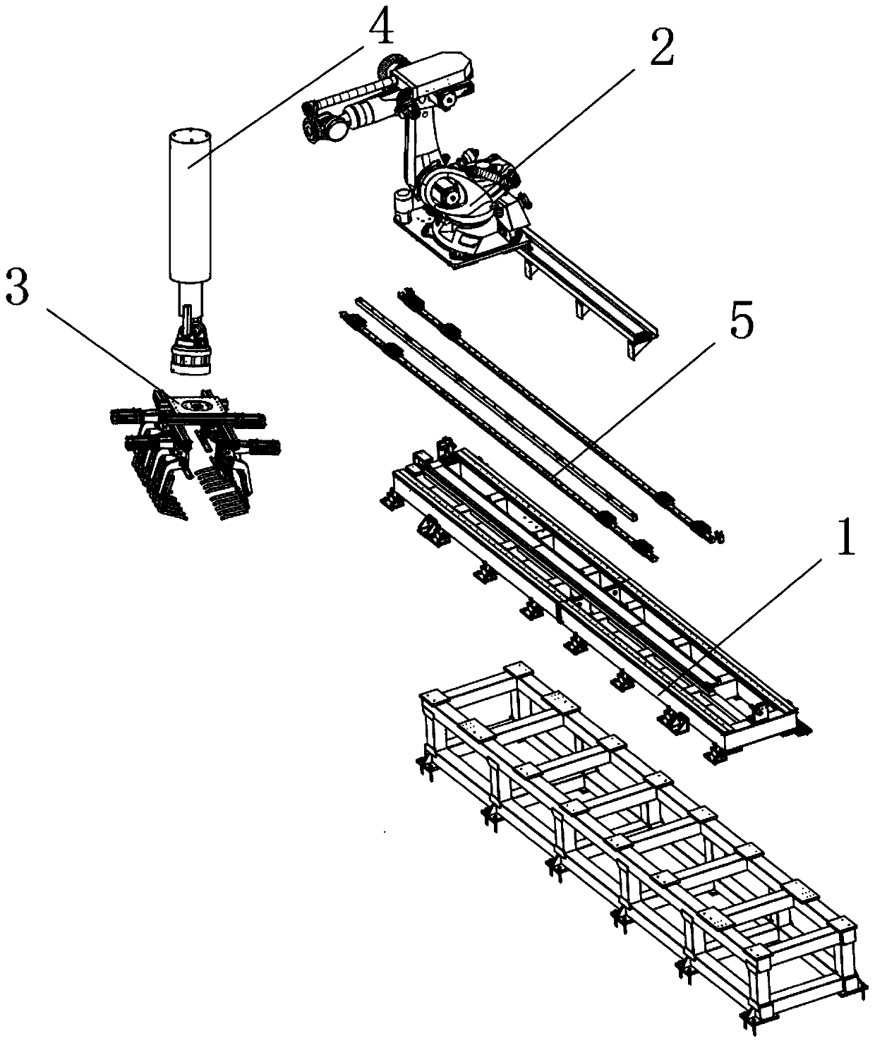
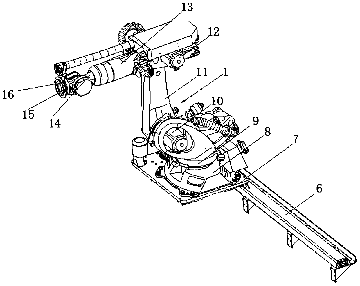
[0049] see Figure 1-12 As shown, a fixture for robot parts processing with multi-angle fixing function, including a mounting table 1, a movable plate 2 and a clamping seat 3, the movable plate 2 is arranged above the mounting table 1, and the clamping seat 3 is arranged on the movable plate 2 below one end;

[0050] A bottom support plate 7 is horizontally arranged below the movable plate 2, and a supporting plate 6 is arranged below one end of the bottom support plate 7. When the bottom support plate 7 moves, the support...


PUM

PropertyMeasurementUnit
Rotatable angleaaaaaaaaaa

Abstract

The invention discloses a robot part processing clamp with a multi-angle fixing function. The robot part processing clamp comprises an installing platform, a movable disc and a clamping seat, the movable disc is arranged above the installing platform, the clamping seat is arranged below one end of the movable disc, and a bottom support plate is horizontally arranged below the movable disc. The robot part processing clamp has the beneficial effects that robot parts are clamped and fixed through a plurality of equally-spaced clamping jaws, it is ensured that the robot parts can be processed by aprocessing instrument more conveniently, efficiently and stably; a transferring and connecting seat drives the clamping seat to move front and back on the installing platform to adjust the position,on one hand, the position of processing of the robot parts by the processing instrument is more precise and adjustable, on the other hand, it is ensured that after the robot parts are processed, and the robot parts can be quickly and conveniently transferred and put to the specific position to be arranged; and a first motor drives the clamping seat to rotate by 360 degrees to ensure that the moving, transferring and putting efficiency of the robot parts is high and the scope is wider.

Description

technical field [0001] The invention relates to a jig, in particular to a jig for processing robot parts with a multi-angle fixing function, and belongs to the application technical field of jigs for processing robot parts. Background technique [0002] When the robot parts are processed, the fixtures are used more and more frequently. The robot parts are grasped and fixed through the fixtures, and the appropriate angle and position of the robot parts are adjusted to facilitate the processing equipment to better and faster the robot parts. for processing. [0003] The existing fixtures for robot parts processing still have many deficiencies in use. The existing robot parts processing fixtures are not enough to adjust the position and angle of the robot parts to be processed after the robot parts are grasped and fixed. It is convenient, fast, and accurate, and the range of position and angle that the fixture can adjust the processing of robot parts is small. The efficiency ...

Claims


Application Information

Patent Timeline
IPC IPC(8): B25J5/02B25J9/12B25J9/14B25J15/02B25J15/08
CPCB25J5/02B25J9/126B25J9/144B25J15/0206B25J15/08
Inventor 刘萍张书玮
Owner XUZHOU COLLEGE OF INDAL TECH
Learn More