
Digital multi-beam angle-measuring method and system based on single receiving channel

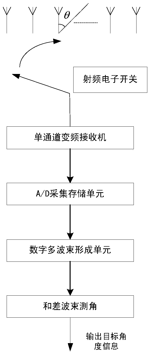
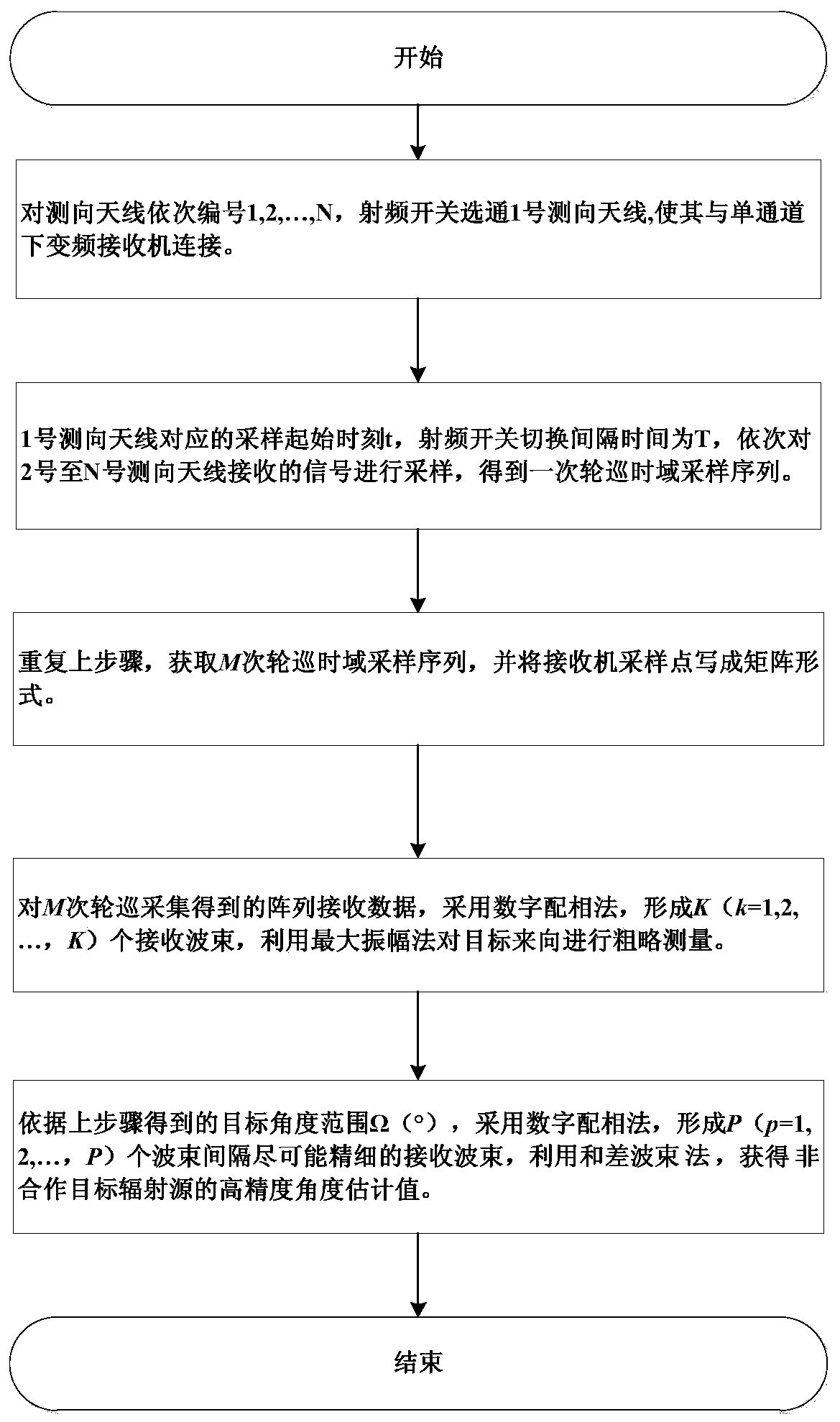
A digital multi-beam, receiving channel technology, applied in radio wave measurement systems, radio wave direction/deviation determination systems, direction finders using radio waves, etc. The problem of high cost of the direction method can achieve real-time and accuracy assurance, meet the needs of over-the-horizon detection, and avoid the effect of direction finding performance degradation.

Active Publication Date: 2019-07-26
XIAN INSTITUE OF SPACE RADIO TECH
View PDF5 Cites 9 Cited by
  • Summary
  • Abstract
  • Description
  • Claims
  • Application Information

AI Technical Summary

Problems solved by technology

[0003] The purpose of the present invention is to overcome the deficiencies of the prior art, provide a digital multi-beam angle measurement method and system based on a single receiving channel, and solve the problems caused by the high cost of the multi-receiving channel direction finding method, complex hardware and inconsistent amplitude and phase between multiple channels. The problem of direction finding performance degradation; solve the problem of low receiving sensitivity of the single-channel super-resolution spatial spectrum direction finding system, high complexity of direction finding calculations, and insufficient real-time direction finding performance

Method used


Image

  • Digital multi-beam angle-measuring method and system based on single receiving channel
  • Digital multi-beam angle-measuring method and system based on single receiving channel
  • Digital multi-beam angle-measuring method and system based on single receiving channel

Examples


Embodiment

[0076] A specific implementation case of a digital multi-beam angle measurement method based on a single receiving channel is given, and the specific implementation is as follows:

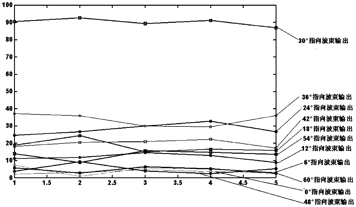
[0077] It is assumed that N=16 isotropic DF antennas are evenly distributed on a straight line, and the distance between adjacent DF antennas is d=λ / 2=(3e8 / 3.5e9) / 2=0.0429m. A far-field narrowband plane wave signal Incident to the uniform linear array at an azimuth angle θ=30°, where λ represents the center frequency f of the s(t) signal 0 = The wavelength corresponding to 3.5GHz. ;

[0078] (1) Assuming that the received signal of the array is superimposed with a Gaussian white noise sequence, the signal-to-noise ratio SNR=15dB, and the switching rate of the radio frequency electronic switch is 15MHz, then the time-domain sampling sequence X obtained by one polling is as follows:

[0079] Table 1 A round-robin time-domain sampling sequence

[0080] 4.89086138981063+0.190670383095548i...


PUM


Abstract

The invention discloses a digital multi-beam angle-measuring method and system based on a single receiving channel. Direction-finding antennas share a receiving channel and an A / D acquisition and storage unit; received signals of the antennas are sampled in sequence through a radio-frequency switch at the same time interval; a plurality of receiving beams are formed in a digital domain for array receiving data constructed by repeated rotational sampling; and then passive high-accuracy angle measurement for a non-cooperative target radiation source by adopting sum and difference beam angle measurement. Compared with a multi-receiving-channel direction-finding system, the digital multi-beam angle-measuring system has remarkable advantages on the aspects of cost and system complexity, and degradation of the direction-finding performance due to inconsistent amplitude phases between channels is avoided. Compared with a classic super-resolution spatial spectrum direction-finding technology,the digital multi-beam angle-measuring system has higher receiving sensitivity, is particularly suitable for detecting weak power signals such as various sky waves, scattering and sidelobe, and meetsthe demand of beyond visual range detection. Only multiplication and addition operations are used in the multi-beam forming and angle measurement process, and the feature decomposition and the spectrum peak search operation of a large-scale data matrix are not involved, so that both the real-time performance and the accuracy are ensured.

Description

technical field [0001] The invention belongs to the field of array signal processing, and mainly relates to a method based on a single receiving channel, simultaneously forming multiple receiving beams in the digital domain, and completing passive high-precision angle measurement of non-cooperative target radiation sources. Background technique [0002] After decades of intensive research, direction finding algorithms based on array processing have been greatly developed. Whether it is a direction finding method based on analog or digital multi-beam amplitude comparison or phase comparison, or a super-resolution spatial spectrum estimation method based on subspace decomposition, multiple antennas need to be sampled in parallel at the same time, so the number of array antennas is closely related to the down-conversion receiving channel and The A / D acquisition and storage devices correspond to the numbers one by one. In order to obtain excellent angle estimation performance a...

Claims


Application Information

Patent Timeline
Patent Type & Authority Applications(China)
IPC IPC(8): G01S3/14
CPCG01S3/143
Inventor 陈显舟杨旭白琳方海赵扬李聪
Owner XIAN INSTITUE OF SPACE RADIO TECH
Learn More