Delay measurement method, device and system for direct current transmission system
A technology of direct current transmission system and measurement method, which is applied in the direction of measuring devices, measuring electricity, and measuring electrical variables, etc., can solve problems such as system outage and damage to user equipment, and achieve the effect of reducing difficulty and delay error
- Summary
- Abstract
- Description
- Claims
- Application Information
AI Technical Summary
Problems solved by technology
Method used
Image


Examples
Embodiment 1
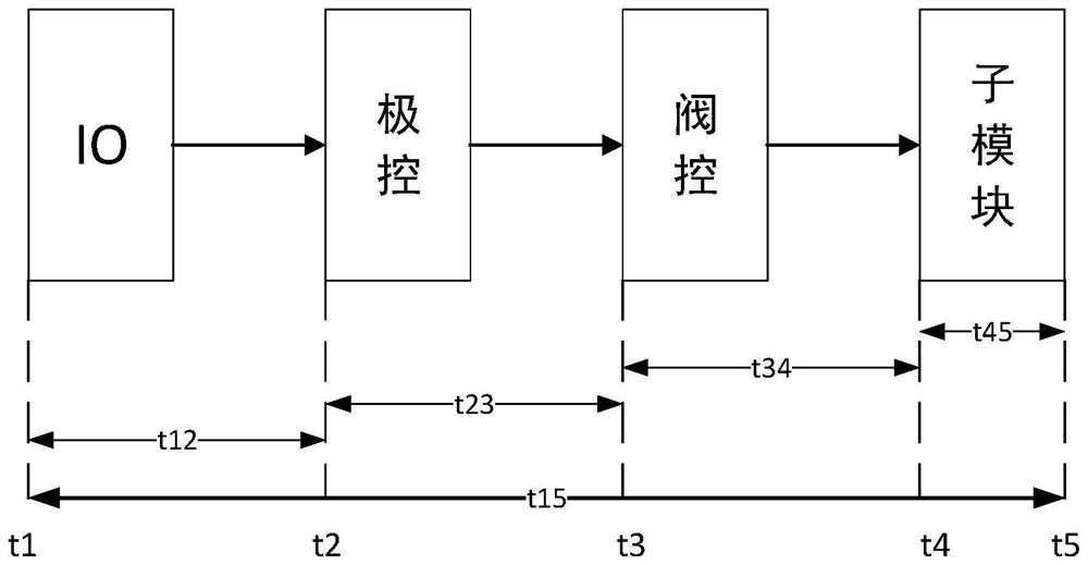
[0036] A delay measurement method for a direct current transmission system, which divides the delay of the entire link of the direct current transmission system into four parts: IO interface link delay, pole control link delay, valve control link delay, sub-module Perform link delay; each part of the link delay starts from the time it receives a signal and ends when it sends the signal to the lower-level system;
[0037] The delay test signal is a periodic sine wave or square wave signal, the signal contains a zero-crossing point, and the signal amplitude and period can be adjusted;
[0038] The delay measurement signal is connected to the link to be tested of the direct current transmission system; the connected delay test signal is an electrical signal or an optical signal; the terminal signal of the link to be tested undergoes photoelectric conversion to convert the optical signal into an electrical signal; The delay of the link to be tested is calculated according to the d...
Embodiment 2
[0047] Delay measurement is performed on the whole of the DC transmission system, that is, the measurement figure 1 In the t15 time, the measurement method specifically includes the following steps:
[0048] Step 1: Connect the delay measurement signal to the link to be tested of the DC transmission system. In this embodiment, the electrical signal of the delay measurement signal is added at the terminal of the IO device. In this embodiment, the delay measurement signal adopts a sine wave. The measurement point is t1.
[0049] Step 2: The extreme control system synchronously processes the sine wave into a square wave, and sends it to the valve control system as a reference wave; the conversion function of synchronously processing the sine wave into a square wave is as follows:
[0050]
[0051] In the formula, ε is the deviation value, which is a non-negative rational number, x[n] is the value of the current cycle delay test signal, x[n-1] is the value of the previous cycl...
Embodiment 3
[0059] Delay measurement of the valve control link of the direct current transmission system, that is, measurement figure 1 In the t34 time, the measurement method specifically includes the following steps:
[0060] Step 1: Connect the delay measurement signal to the link to be tested in the DC transmission system. In this embodiment, the optical signal of the square wave reference wave signal is input into the valve control system, and the measuring point is at t3; in this embodiment The square wave reference wave signal can be generated by an external delay measurement device or directly by a level control device.
[0061] Step 2: The valve control system generates a modulation signal according to the reference wave, and sends it to the sub-module, and the measuring point is at t4.
[0062] Step 3: The terminal signal of the link to be tested, that is, the signal at the measurement point t4, is converted into an electrical signal through photoelectric conversion.
[0063] ...
PUM
 Abstract
Description
Claims
Application Information
 - R&D
- Intellectual Property
- Life Sciences
- Materials
- Tech Scout
- Unparalleled Data Quality
- Higher Quality Content
- 60% Fewer Hallucinations
Browse by: Latest US Patents, China's latest patents, Technical Efficacy Thesaurus, Application Domain, Technology Topic, Popular Technical Reports.
© 2025 PatSnap. All rights reserved.Legal|Privacy policy|Modern Slavery Act Transparency Statement|Sitemap|About US| Contact US: help@patsnap.com