
Oil-free air compressor for automobile

An air compressor and air compression technology, applied in the direction of mechanical equipment, machines/engines, liquid variable capacity machinery, etc., can solve the problems of large space occupation, limited life of air compressors, vibration, etc., to eliminate vibration and noise, Reasonable design and layout, good transmission stability

Pending Publication Date: 2019-07-26
浙江万安其弗汽车零部件有限公司
View PDF0 Cites 0 Cited by
  • Summary
  • Abstract
  • Description
  • Claims
  • Application Information

AI Technical Summary

Problems solved by technology

[0003] (1) The main shaft of the air compressor is connected to the output shaft of the driving motor through a coupling, and the connection method of the coupling will cause defects such as vibration and noise;
[0004] (2) The crankshaft and the main shaft of the air compressor or multiple crankshafts are usually connected by couplings or keys, which also have the defects of large vibration and noise;
[0005] (3) The cooling performance of the air compression device is poor, so that the continuous working time is limited and the life of the air compressor is limited;
[0006] (4) The electric air compressors currently used in the market are mainly oil-lubricated. When the oil-lubricated air compressor is exhausted, part of the lubricating oil is discharged with the compressed air, resulting in system failures such as braking.
And it needs to be equipped with an oil cooling system, which is large in size, takes up a lot of space, heavy in weight and prone to oil leakage failures

Method used


Image

  • Oil-free air compressor for automobile
  • Oil-free air compressor for automobile
  • Oil-free air compressor for automobile

Examples


Embodiment Construction

[0063] In order to make the object, technical solution and advantages of the present invention clearer, the present invention will be further described in detail below in conjunction with the accompanying drawings and embodiments. It should be understood that the specific embodiments described here are only used to explain the present invention, not to limit the present invention.

[0064] In the description of the present invention, it should be understood that the orientation or positional relationship indicated by the terms "upper", "lower", "front", "rear", "inner", "outer" etc. Orientation or positional relationship is only for the convenience of describing the present invention and simplifying the description, and does not indicate or imply that the referred device or element must have a specific orientation, be constructed and operated in a specific orientation, and thus should not be construed as a limitation of the present invention.

[0065] In the description of the...


PUM


Abstract

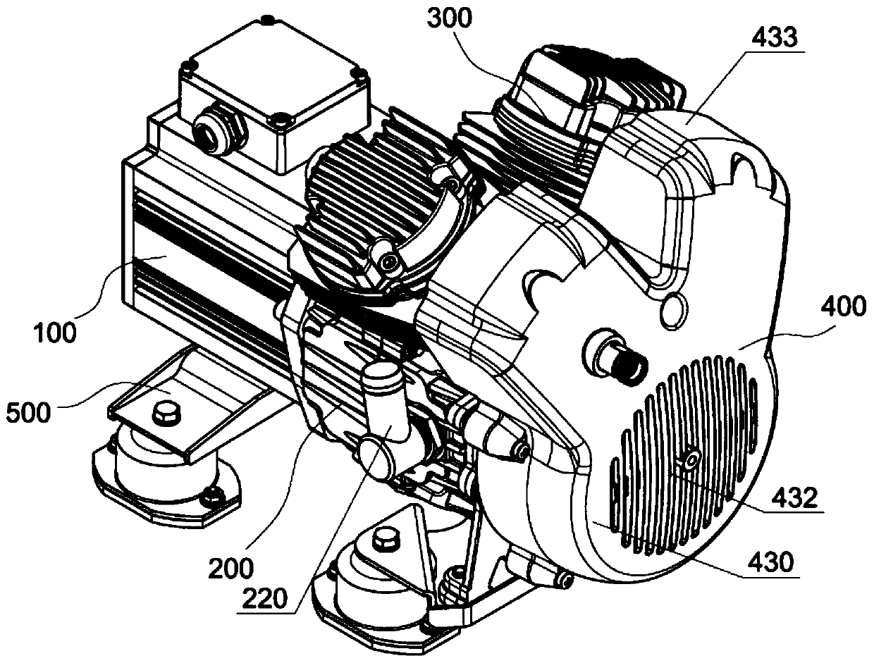
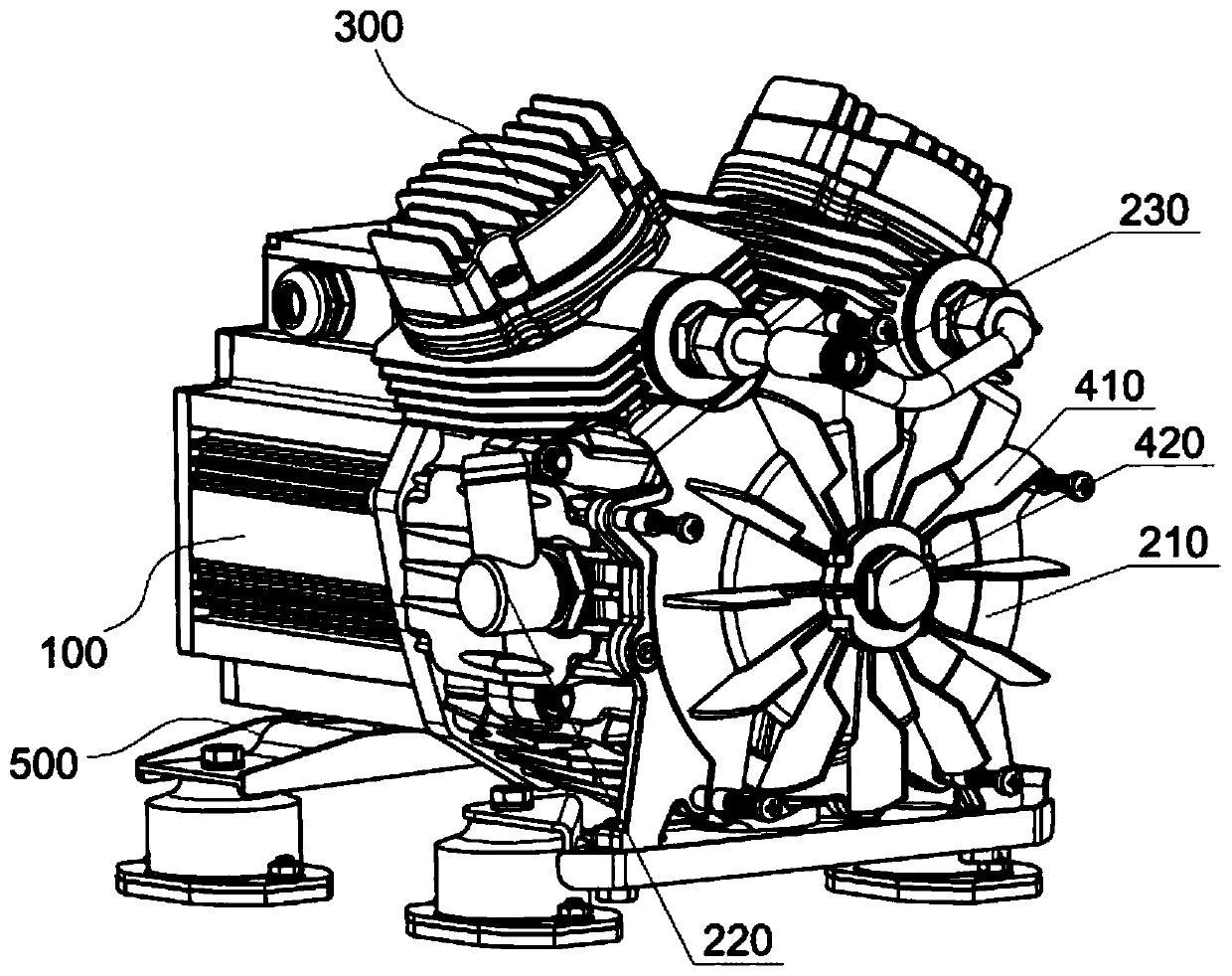
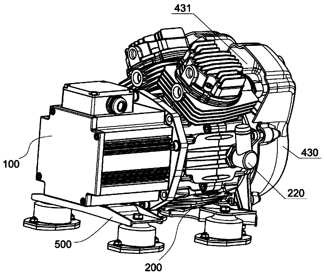
The invention relates to the technical field of air compressors, in particular to an oil-free air compressor for an automobile. The oil-free air compressor for the automobile comprises an electromotor, a crankcase, and at least one air compression device arranged on a spindle box, wherein the air compression device at least comprises an air cylinder, a piston, a connecting rod, a drive shaft and acrank; the drive shaft is an output shaft of the electromotor; a connection external screw thread is arranged at the position, close to the electromotor, on the drive shaft; a connection internal screw thread adaptive to the connection external screw thread is arranged on one side, close to a drive motor, of a rotary shaft hole of the crank; and when the drive shaft is at the rotating state, a relatively screwing trend exists between the connection external screw thread and the connection internal screw thread. According to the oil-free air compressor for the automobile provided by the embodiment, the output shaft of the electromotor and the drive shaft of the air compressor are of an integrated structure, so that compared with the prior art that an output shaft of an electromotor is connected with a drive shaft through a coupler, the defects of vibration and noise caused by the coupler are eliminated, the transmission stability is better, and the transmission precision is higher.

Description

technical field [0001] The invention relates to the technical field of air compressors, in particular to an oil-free air compressor for vehicles. Background technique [0002] The electric air compressor is the main body of the air source device. It is a device that converts the mechanical energy of the prime mover (usually an electric motor) into gas pressure energy, and is a pressure generating device for compressing air. Common electric air compressors currently on the market have the following technical defects: [0003] (1) The main shaft of the air compressor is connected to the output shaft of the driving motor through a coupling, and the connection method of the coupling will cause defects such as vibration and noise; [0004] (2) The crankshaft and the main shaft of the air compressor or multiple crankshafts are usually connected by couplings or keys, which also have the defects of large vibration and noise; [0005] (3) The cooling performance of the air compress...

Claims


Application Information

Patent Timeline
IPC IPC(8): F04B35/04F04B39/00F04B39/02F04B39/06F04B39/10F04B27/04
CPCF04B35/04F04B39/0094F04B39/0284F04B39/1046F04B27/005F04B27/0409F04B39/102F04B39/066
Inventor 肖东明姚灿均王玉亮
Owner 浙江万安其弗汽车零部件有限公司
Learn More