Controllable rotating chandelier

A technology for chandeliers and light poles, applied in the field of daily life, can solve problems such as single style of chandeliers, failure to bring people visual effects, insufficient demand for chandeliers, etc., to achieve a stable overall structure, increase the viewing effect, and improve the effect of use

Pending Publication Date: 2019-07-23
曹普钟
View PDF0 Cites 0 Cited by
  • Summary
  • Abstract
  • Description
  • Claims
  • Application Information

AI Technical Summary

Problems solved by technology

Pendant lamps are very common in modern indoor lighting, especially in homes. They can effectively improve the decoration level and have good lighting effects. Therefore, they are deeply loved by consumers. However, the styles of pendant lamps sold in the market are relatively single. Moreover, it only has static lighting effects, which cannot bring people better visual effects, and it is still insufficient in people's demand for chandeliers.

Method used


Image

  • Controllable rotating chandelier
  • Controllable rotating chandelier
  • Controllable rotating chandelier

Examples


Embodiment Construction

[0016] The following will clearly and completely describe the technical solutions in the embodiments of the present invention with reference to the accompanying drawings in the embodiments of the present invention. Obviously, the described embodiments are only some, not all, embodiments of the present invention. Based on the embodiments of the present invention, all other embodiments obtained by persons of ordinary skill in the art without creative work, any modifications, equivalent replacements, improvements, etc., shall be included in the protection scope of the present invention Inside.

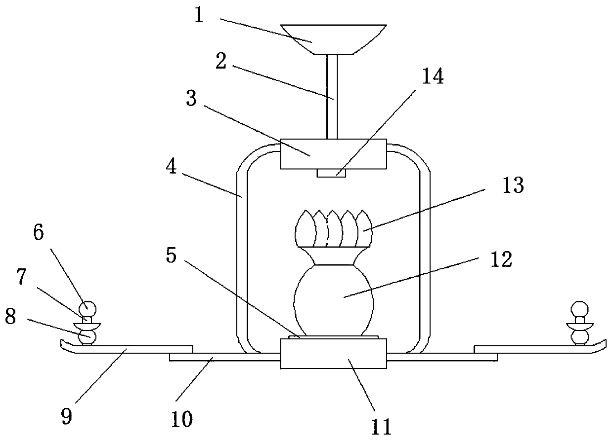
[0017] Such as figure 1 , figure 2 As shown, a controllable rotating chandelier includes a lamp stand, and the lamp stand includes a hanging cup 1, a hanging rope 2, a first junction box 3, a second junction box 11, a connecting bending rod 4, a first light pole 10, The second light pole 9; the hanging rope 2, the connecting bent pole 4, the first light pole 10, and the second light po...


PUM


Abstract

The invention discloses a controllable rotating chandelier. The chandelier comprises a lamp holder, the lamp holder comprises an upper hanging handleless cup, a hanging rope, a first wiring box, a second wiring box, connecting curved rods, a first light pole and a second light pole; the upper hanging handleless cup is fixedly connected with one end of the hanging rope, the other end of the hangingrope is fixedly connected with the upper end of the first wiring box, the bottom end of the first wiring box is provided with a first illuminating lamp, the side surface of the first wiring box is fixedly connected with the side surface the second wiring box through a plurality of the connecting curved rods, the second wiring box is internally provided with a rotating motor, the output shaft of the rotating motor is fixedly connected with a decorative bottle on the upper end surface of the second wiring box, and the top end of the decorative bottle is fixedly connected with a petal-shaped decorative plate; a LED light board sleeves the bottom end of the decorative bottle, and the bottom end of the LED light board is fixedly connected to the upper end surface of the second wiring box; theside surface of the second wiring box is fixedly connected with one end of the first light pole, the other end of the first light pole is fixedly connected to the second light pole, the upper end surface of the second light pole is fixedly connected to a lamp stand, and a second lamp is disposed on the lamp stand.

Description

technical field [0001] The invention relates to the field of daily life, in particular to a controllable rotating chandelier. Background technique [0002] With the rapid development of social economy and the improvement of people's living standards, a single first lighting fixture can no longer meet the needs of people's daily life. Therefore, chandeliers with changeable shapes have appeared. Pendant lamps are very common in modern indoor lighting, especially in homes. They can effectively improve the decoration level and have good lighting effects. Therefore, they are deeply loved by consumers. However, the styles of pendant lamps sold in the market are relatively single. And it only has static lighting effects, which cannot bring people better visual effects, and it is still insufficient in people's demand for chandeliers. Contents of the invention [0003] The purpose of the present invention is to solve the above problems and provide a controllable rotating chandelie...

Claims


Application Information

Patent Timeline
Patent Type & Authority Applications(China)
IPC IPC(8): F21S8/06F21V21/104F21V23/00F21V21/15F21V33/00F21V19/00F21Y115/10
CPCF21S8/061F21V19/003F21V21/104F21V21/15F21V23/001F21V33/00F21Y2115/10
Inventor 曹普钟
Owner 曹普钟
Why Eureka
Try Eureka