
A hanger for easy adjustment of parts during assembly

A technology for parts and hangers, applied in the field of mechanical processing, can solve the problems of inability to disassemble and meet the requirements of use, and achieve the effect of preventing the workpiece from falling off, facilitating automatic disassembly and assembly, and realizing convenience.

Active Publication Date: 2020-01-03
安徽中巨机电设备有限公司
View PDF8 Cites 0 Cited by
  • Summary
  • Abstract
  • Description
  • Claims
  • Application Information

AI Technical Summary

Problems solved by technology

[0003] When there are many parts in the vehicle that need to be shot blasted, it is necessary to hang the workpiece on the hanger, and then put the hanger into the shot blasting machine to perform shot blasting on the workpiece, but now it is convenient to adjust the parts during assembly The hanger is generally an integral component, which cannot be disassembled, and the existing hanger cannot be used to automatically mount the workpiece, which cannot meet the current use requirements

Method used


Image

  • A hanger for easy adjustment of parts during assembly
  • A hanger for easy adjustment of parts during assembly
  • A hanger for easy adjustment of parts during assembly

Examples


Embodiment 1

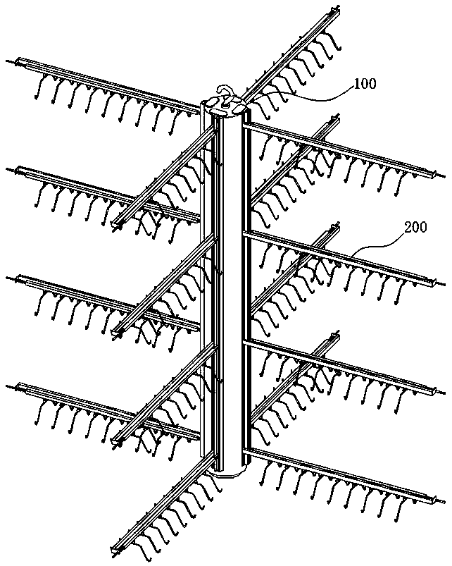
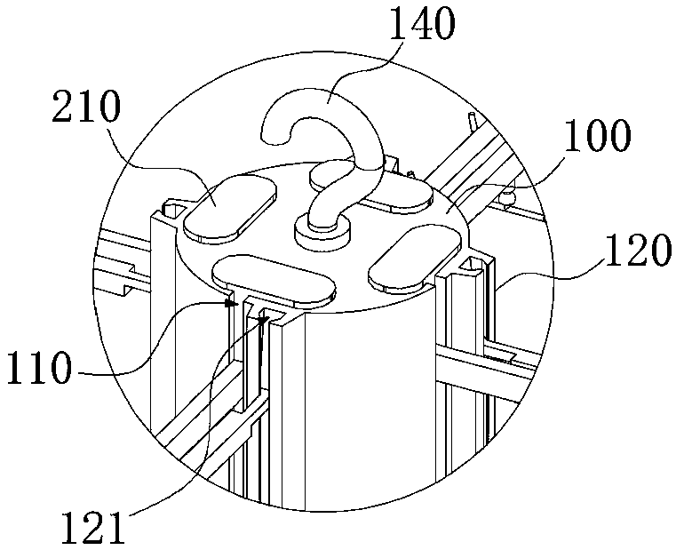
[0040] refer to Figure 1-5 , in the embodiment of the present invention, a hanger that is convenient for adjusting parts during assembly is proposed, including a hook 300, a hanger 200 and a hanger main body 100, the hook 300 is installed on the hanger 200, and the hook 300 is used for hanging The workpiece, the hanger 200 is detachably installed on the hanger main body 100 , and the hanger main body 100 is used to support the hanger 200 .

[0041] The present invention divides the step of hooking the workpiece into two steps through the setting of the split hanger 200 and the hanger main body 100. In the first step, each hanger 200 is first hung on the workpiece, and then each hanger 200 is assembled. On the main body 100 of the hanger, the action is clear, which is convenient for automatic hooking of workpieces. At the same time, the main body 100 of the hanger can integrate multiple sets of hangers 200, which greatly improves the loading capacity and can provide stable sup...

Embodiment 2

[0065] refer to Figure 4~6 , according to a hanger that is convenient for adjusting parts during assembly proposed by the present invention, a shot blasting machine hanger is proposed in the embodiment of the present invention, including a support rod 210, a fixed rod 220, a movable rod 230 and a hook 300, The fixed rod 220 is installed on the support rod 210, the support rod 210 and the fixed rod 220 are arranged crosswise, the fixed rod 220 and the movable rod 230 are correspondingly arranged in parallel, the hook 300 is movably connected to the fixed rod 220 and the movable rod 230, and the hook 300 is used to mount the workpiece , the movable rod 230 is used to drive the hook 300 to rotate, so that the projection length of the hook 300 on a vertical plane is adjustable, and the vertical plane is perpendicular to the fixed rod 220 .

[0066] The present invention realizes the supporting function to the fixed rod 220 and the hook 300 through the setting of the support rod 2...


PUM


Abstract

The invention relates to a rack for conveniently adjusting parts during assembly. The rack comprises hooks, hangers and a rack body. The hooks are mounted on the hangers and used for hanging workpieces, the hangers are detachably mounted on the rack body, and the rack body is used for supporting the hangers. The rack is stable in structure and reasonable in layout, the hangers can be detachably connected with the rack body, the hangers can be conveniently dismounted and mounted automatically through a machine, automation can be conveniently achieved, and the machining efficiency can be effectively improved.

Description

technical field [0001] The invention relates to the field of mechanical processing, in particular to a hanger which is convenient for adjusting parts during assembly. Background technique [0002] Shot blasting machine refers to casting equipment that uses high-speed projectiles thrown by a shot blaster to clean or strengthen the surface of castings. The shot blasting machine can shake out sand, remove the core and clean the castings at the same time. It is a processing technology that blasts steel sand and steel shots at high speed and impacts on the surface of the material object through the shot blasting machine. It is faster and more efficient than other surface treatment techniques and can be used for part retention or post-stamping casting processes. [0003] When there are many parts in the vehicle that need to be shot blasted, it is necessary to hang the workpiece on the hanger, and then put the hanger into the shot blasting machine to perform shot blasting on the w...

Claims


Application Information

Patent Timeline
Patent Type & Authority Patents(China)
IPC IPC(8): C21D7/06
CPCC21D7/06
Inventor 王六四王少波程飞邓静
Owner 安徽中巨机电设备有限公司
Learn More