Milling machine sliding platform for placing machined part

A technology for sliding platforms and processed parts, which is applied in the direction of metal processing machinery parts, metal processing equipment, manufacturing tools, etc., and can solve problems affecting the working efficiency of sliding platforms

Inactive Publication Date: 2019-07-23
南安市跃启机械制造有限公司
View PDF4 Cites 1 Cited by
  • Summary
  • Abstract
  • Description
  • Claims
  • Application Information

AI Technical Summary

Problems solved by technology

[0003] Place the workpiece on the sliding platform of the milling machine for processing. In order to ensure the machining accuracy, the workpiece needs to be fixed on the sliding platform, so as to ensure that the workpiece is not displaced by other external forces. However, in this way of fixing, after the fixed workpiece is processed It is necessary to manually disassemble the workpiece from the fixed groove, which affects the working efficiency of the sliding platform

Method used


Image

  • Milling machine sliding platform for placing machined part
  • Milling machine sliding platform for placing machined part
  • Milling machine sliding platform for placing machined part

Examples


Embodiment

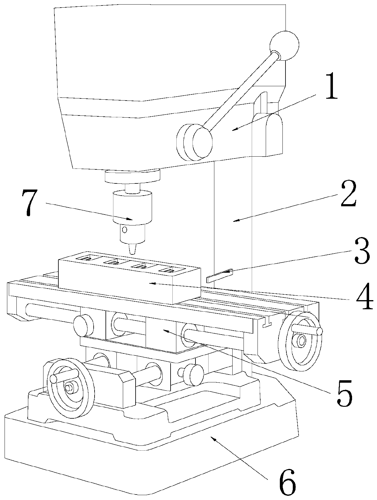
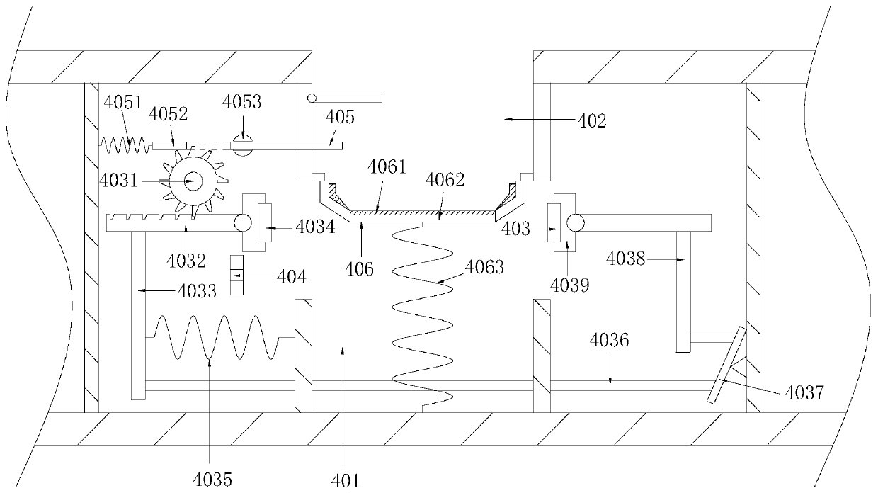
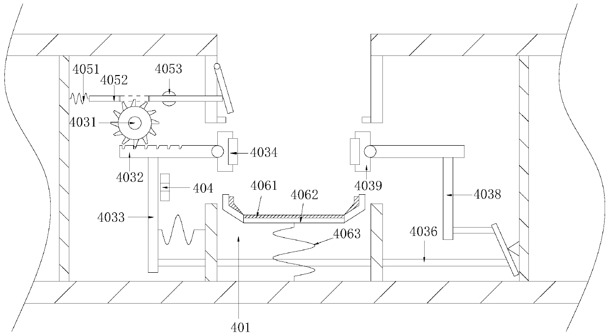
[0028] see Figure 1-Figure 7 , the present invention provides a milling machine sliding platform for placing workpieces. Its structure includes an upper fixed seat 1, a main support column 2, a fixed extension rod 3, a positioning processing device 4, a workbench 5, a base 6, and a processing head 7. The upper fixing base 1 and the base 6 are set up in a vertical structure, the upper fixing base 1 is located in the north direction of the base 6, the base 6 is fixedly connected with the upper fixing base 1 through the main support column 2, and the upper fixing base 1 A processing head 7 is provided on the side of the fixed seat 1 facing the base 6, and the processing head 7 is mechanically matched with the positioning processing device 4, and the positioning processing device 4 is installed on the workbench 5, and the workbench 5 Fixedly connected with the base 6, the fixed extension rod 3 is arranged on the end of the main support column 2 close to the workbench 5, and the f...


PUM


Abstract

The invention discloses a milling machine sliding platform for placing a machined part. The milling machine sliding platform structurally comprises an upper fixing seat, a main supporting column, a fixed extending rod, a positioning processing device, a work table, a base and a machining head; and the upper fixing base and the base are arranged to be of upper and lower structures. The milling machine sliding platform has the beneficial effects that a control gear is driven by external mechanical force to rotate counterclockwise, as a gear is engaged with a toothed edge on a driving rod, the driving rod moves in the same direction accordingly, under the action of a reversing mechanism, the transmission direction of the force is changed, two clamping plates move in the opposite direction toclamp the part, and the aim of clamping the to-be-machined part is achieved; the part slides on the work table through slippage, when the part passes through the fixed extending rod, the fixed extending rod and a groove are embedded, a first rod is reset under traction of a rectangular block, clamping force of the part is lost, the part groove drive the part to upwards move under the effect of a third spring, the part can be conveniently taken out, and manual disassembling of the part from the work table is not needed.

Description

technical field [0001] The invention relates to the field of milling machines, in particular to a milling machine sliding platform for placing workpieces. Background technique [0002] The workbench is the workbench used to install the workpiece on the gantry milling machine. There are a number of chutes on the upper end surface of the workbench to facilitate fixing the workpiece. The lower end surface of the workbench is provided with a connecting piece for connecting with the drive mechanism, so that The drive mechanism can drive the table to move flexibly along the guide rail to meet the positioning and processing of the workpiece. The table on the milling machine is required to be able to achieve accurate and stable sliding of the table. Because it affects the processing accuracy of the control product, the current sliding table of the milling machine has The following defects: [0003] Place the workpiece on the sliding platform of the milling machine for processing. I...

Claims


Application Information

Patent Timeline
IPC IPC(8): B23Q1/01B23Q1/26
CPCB23Q1/01B23Q1/26
Inventor 杨小继黄佳彬江增泉庄明忠
Owner 南安市跃启机械制造有限公司
Why Eureka
Try Eureka