
Portable mobile ultrasonic testing device for medical ultrasonic equipment

A technology of ultrasonic detection and ultrasonic equipment, applied in the direction of ultrasonic/sonic/infrasonic diagnosis, application, medical science, etc., can solve problems such as inconvenient, unfavorable for patients to rest, waste of time, etc., and achieve the effect of convenient adjustment and convenient movement

Active Publication Date: 2019-07-23
文静
View PDF7 Cites 1 Cited by
  • Summary
  • Abstract
  • Description
  • Claims
  • Application Information

AI Technical Summary

Problems solved by technology

[0002] Most of the traditional ultrasonic detection devices are fixed in the detection room, and patients need to go to the fixed detection room for inspection when they need to undergo ultrasound examination. Every time a patient needs to be supported by family members or medical staff or sent to the examination room with wheelchairs and other tools, traditional testing equipment is inconvenient to adjust the patient’s lying angle, is not conducive to the patient’s rest, and wastes a lot of time. It is necessary to design an ultrasonic detection device that is convenient to move to the patient's side and convenient for the patient to go up and down.

Method used


Image

  • Portable mobile ultrasonic testing device for medical ultrasonic equipment
  • Portable mobile ultrasonic testing device for medical ultrasonic equipment
  • Portable mobile ultrasonic testing device for medical ultrasonic equipment

Examples


Embodiment Construction

[0013] In order to make the purpose, technical solutions and advantages of the embodiments of the present invention clearer, the technical solutions in the embodiments of the present invention will be clearly and completely described below in conjunction with the drawings in the embodiments of the present invention. Obviously, the described embodiments It is a part of embodiments of the present invention, but not all embodiments. Based on the embodiments of the present invention, all other embodiments obtained by persons of ordinary skill in the art without creative efforts fall within the protection scope of the present invention.

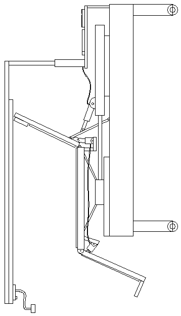
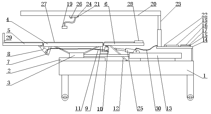
[0014] A portable mobile ultrasonic testing device for medical ultrasonic equipment, as shown in the figure, includes a mounting plate 1, a first horizontal rail 2 is fixedly installed on the upper left end of the mounting plate 1, and the first horizontal rail 2 is parallel to the length direction of the mounting plate 1. The upper part of the fi...


PUM


Abstract

The invention relates to a portable mobile ultrasonic testing device for medical ultrasonic equipment. The portable mobile ultrasonic testing device comprises a mounting plate, wherein a first horizontal rail is fixedly mounted at the upper part of the left end of the mounting plate, and is parallel to the length direction of the mounting plate; a sliding seat is mounted at the upper part of the first horizontal rail in a cooperation manner; a first horizontal plate is arranged above the upper part of the sliding seat; the bottom of the first horizontal plate is fixedly connected with the sliding seat through a bracket; the left end of the first horizontal plate is in hinging connection with the right end of a second horizontal plate; the right end of the first horizontal plate is in hinging connection with the left end of a third horizontal plate; an oblique plate is fixedly mounted at the bottom of the left end of the second horizontal plate; the lower end of the oblique plate slopesfacing the direction of the left end of the second horizontal plate; and the lower end of the oblique plate is in hinging connection with a position adjacent to the right end, of the bottom of the second horizontal plate, through an oblique first hydraulic rod. The portable mobile ultrasonic testing device disclosed by the invention is convenient to move; medical staff can push the portable mobile ultrasonic testing device beside a patient, the patient can conveniently move to the upper part of the portable mobile ultrasonic testing device for ultrasonic testing, so that the patients which are not convenient to move do not need to arrive at specialized administration offices for inspection.

Description

technical field [0001] The invention belongs to the technical field of medical testing equipment, in particular to an ultrasonic testing device for portable mobile medical ultrasonic equipment. Background technique [0002] Most of the traditional ultrasonic detection devices are fixed in the detection room, and patients need to go to the fixed detection room for inspection when they need to undergo ultrasound examination. Every time a patient needs to be supported by family members or medical staff or sent to the examination room with wheelchairs and other tools, traditional testing equipment is inconvenient to adjust the patient’s lying angle, is not conducive to the patient’s rest, and wastes a lot of time. It is necessary to design an ultrasonic detection device that is convenient to move to the patient and convenient for the patient to go up and down. Contents of the invention [0003] The invention provides an ultrasonic detection device for portable mobile medical ...

Claims


Application Information

Patent Timeline
Patent Type & Authority Applications(China)
IPC IPC(8): A61B8/00
CPCA61B8/40A61B8/4405
Inventor 文静
Owner 文静
Learn More