Pull-out type power distribution cabinet convenient for fixing multiple pieces of equipment

A pull-out, power distribution cabinet technology, applied in pull-out switch cabinets, electrical components, switchgear and other directions, can solve the problems of time-consuming and laborious, inconvenient inspection and maintenance of a single electrical equipment, and achieve the effect of fast and automatic fixing

Inactive Publication Date: 2019-07-19
新疆南开电气有限公司
View PDF7 Cites 0 Cited by
  • Summary
  • Abstract
  • Description
  • Claims
  • Application Information

AI Technical Summary

Problems solved by technology

[0005] The purpose of the present invention is to provide a pull-out type power distribution cabinet that is convenient for fixing multiple devices, so as to solve the problem that the sliding support partition of the pull-out type power distribution cabinet proposed in the above-mentioned background technology will be used when installing and connecting electrical equipment. Each electrical device is fixedly connected to the partition board separately through screws and other connectors, which is time-consuming and labor-intensive, but if all the electrical devices placed on the sliding partition board are fixed and pressed through a board, it is inconvenient for a single electrical device Problems with inspection and maintenance

Method used


Image

  • Pull-out type power distribution cabinet convenient for fixing multiple pieces of equipment
  • Pull-out type power distribution cabinet convenient for fixing multiple pieces of equipment
  • Pull-out type power distribution cabinet convenient for fixing multiple pieces of equipment

Examples


Embodiment Construction

[0024] The following will clearly and completely describe the technical solutions in the embodiments of the present invention with reference to the accompanying drawings in the embodiments of the present invention. Obviously, the described embodiments are only some, not all, embodiments of the present invention. Based on the embodiments of the present invention, all other embodiments obtained by persons of ordinary skill in the art without making creative efforts belong to the protection scope of the present invention.

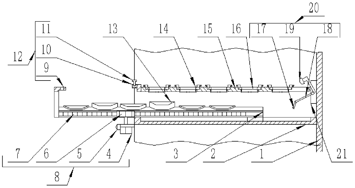
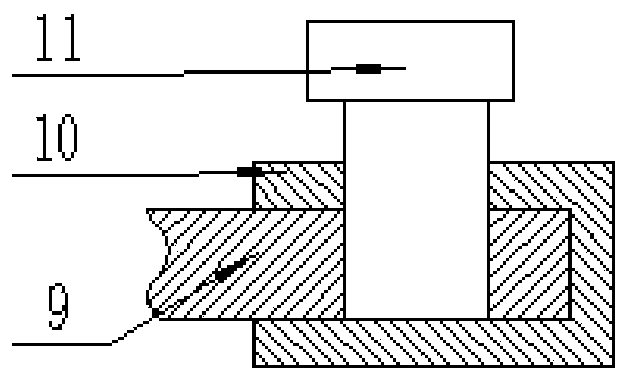
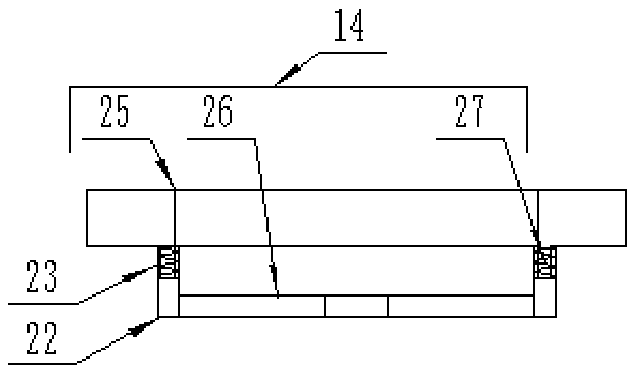
[0025] see Figure 1-5 , the present invention provides a technical solution: a pull-out power distribution cabinet that is convenient for fixing multiple devices, including a cabinet body 1, and the interior of the cabinet body 1 is equidistant from top to bottom with installation slides 3 installed horizontally, and the installation slides 3 The front and rear inner walls of the cabinet body 1 where it is located are horizontally fitted and fixedly welded wi...


PUM


Abstract

The invention discloses a pull-out type power distribution cabinet convenient for fixing multiple pieces of equipment. The pull-pull type power distribution cabinet comprises a cabinet body, wherein mounting sliding plates are horizontally arranged in the cabinet body from top to bottom at equal intervals, and sliding rails are horizontally attached and fixedly welded on the front inner wall and the rear inner wall of the cabinet body where the mounting sliding plates are located; a fixing pressing mechanism is arranged on the upper side of the mounting sliding plates; the fixing pressing mechanism is connected with the cabinet body through a sliding mechanism; and a linkage mechanism is connected to the sliding mechanism. Clamping grooves in the mounting sliding plates are used for placing electrical equipment, so that the mounting sliding plates slide into the cabinet body along with the arranged electrical equipment; when the mounting sliding plates slide into the cabinet body, themounting sliding plates are pressed against a lower pressing plate at the lower end of a bending rotating rod of the linkage mechanism, so that the bending rotating rod is rotated, and an upper pressing plate at the upper end of the bending rotating rod is pressed on the fixing pressing mechanism, and the plate body of the fixing pressing mechanism is pressed to be pressed on the installed electrical equipment in a downward sliding mode along guide rails of the sliding mechanism, and therefore all electrical equipment can be rapidly and automatically fixed.

Description

technical field [0001] The invention relates to the technical field of power distribution cabinets, in particular to a pull-out power distribution cabinet that is convenient for fixing multiple devices. Background technique [0002] Power distribution cabinets are divided into power distribution cabinets, lighting distribution cabinets, and metering cabinets. They are the final equipment of the power distribution system. Power distribution cabinets are collectively referred to as motor control centers. The cabinet is designed to support the installation of electrical equipment as a drawer-type sliding plate body, which is convenient for maintenance; [0003] The traditional pull-out distribution cabinet has the following disadvantages: [0004] Generally, when installing and connecting electrical equipment to the sliding support partitions of pull-out distribution cabinets, each electrical device is fixed and connected to the partitions separately through screws and other c...

Claims


Application Information

Patent Timeline
Patent Type & Authority Applications(China)
IPC IPC(8): H02B11/173
CPCH02B11/173
Inventor 倪存孟
Owner 新疆南开电气有限公司
Why Eureka
Try Eureka