Novel stapler capable of simultaneously binding plurality of nails

A stapler and nail technology, which is applied in the direction of nailing tools, nailing tools, manufacturing tools, etc., can solve the problems of affecting the aesthetic feeling, easily hurting people, and untidy binding desktops, so as to ensure the binding quality and improve the binding quality. Binding efficiency and the effect of improving safety

Pending Publication Date: 2019-07-19
WUYI UNIV
View PDF0 Cites 4 Cited by
  • Summary
  • Abstract
  • Description
  • Claims
  • Application Information

AI Technical Summary

Problems solved by technology

[0003] The existing stapler is generally a single structure, which can only bind one needle at a time, and the angle and position of the stapler are not easy to control, and the staples are easy to be biased, so that the binding is not integrated and affects the aesthetic feeling. When it is necessary to perform multiple bindings, it is time-consuming and laborious, and it is very inconvenient
When the stapler runs out of nails, it needs to take out the nails from the special nail storage box; when it is wrong, it needs to find the staple remover to start the staple again, sometimes it is inconvenient to find the staple remover; After taking it out, it is easy to cause littering
The binding desktop is extremely untidy. In addition, if the binding material is thick, the nails at the rear end of the material are prone to lift, which not only leads to incomplete binding, but also easily hurts people; secondly, when the binding position is not neat, it is easy to nail misplaced
Although the user preliminarily arranges the paper, it is difficult to control the margin distance of the binding during binding, and the binding position is prone to confusion and untidy, which affects reading and beauty; moreover, when the stapler is not in use, the gap between the working part and the base Gaps, easy to pinch hands, and potential safety hazards

Method used


Image

  • Novel stapler capable of simultaneously binding plurality of nails
  • Novel stapler capable of simultaneously binding plurality of nails

Examples


Embodiment Construction

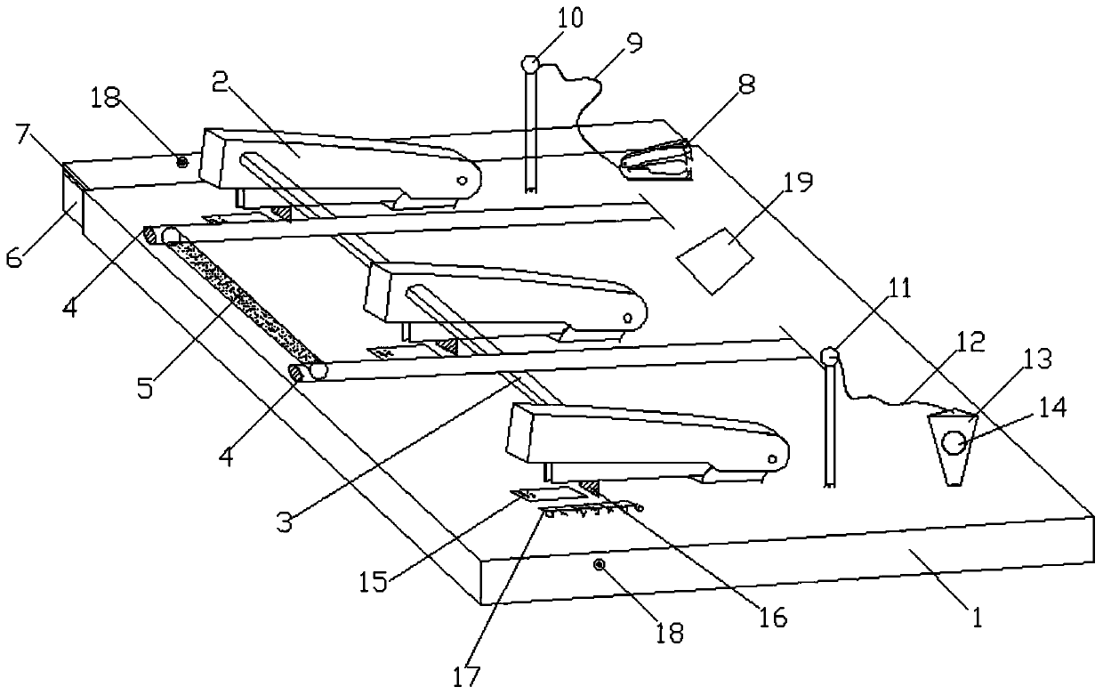
[0024] The specific embodiment of the present invention will be further described below in conjunction with accompanying drawing:

[0025] Such as figure 1 As shown, a novel stapler capable of binding multiple nails at the same time includes a stapler base 1 and a plurality of stapler main bodies 2 arranged on the stapler base 1, and each stapler main body 2 passes through The linkage components are arranged on the base 1 of the stapler. In this embodiment, the number of stapler main bodies 2 is three, and the three stapler main bodies 2 are connected by a linkage connecting rod 3, and corresponding Depressing rod 4, one end of the depressing rod 4 is hinged with the stapler base 1, the other end extends in the direction of the linkage connecting rod 3 and is connected with the linkage connecting rod 3, and the depressing rod 4 presses on the linkage connecting rod 3 , A pressure rod handle 5 is provided between the other ends of the two pressure rods 4 .

[0026] Further, ...


PUM


Abstract

The invention provides a novel stapler capable of simultaneously binding a plurality of nails. The novel stapler comprises a stapler base and a plurality of stapler main bodies arranged on the staplerbase, wherein the plurality of stapler main bodies are connected through a linkage connecting rod, and a pressing rod is further arranged between every two adjacent stapler main bodies; and one end of each pressing rod is hinged to the stapler base, the other end of each pressing rod extends towards the direction of the linkage connecting rod and is connected to the linkage connecting rod, and apressing rod handle is arranged among the other ends of the plurality of pressing rods. The novel stapler has the advantages that the structure is simple, the practicability is high, the plurality ofnails can be bound at the same time through the plurality of stapler main bodies, binding is convenient, the nails can be nailed into a straight line so that different nails are prevented from being staggered, the stress is ensured to be uniform through the pressing rods, then the to-be-bound paper can be nailed stably, and the binding efficiency is further improved; the neatness of the binding area is ensured through a nail storage box; and meanwhile, the raised nails can be flattened through a nail pressing device, the binding quality is ensured, and meanwhile, the user is prevented from being damaged by the raised nails.

Description

technical field [0001] The invention relates to the technical field of staplers, in particular to a novel stapler capable of binding multiple nails at the same time. Background technique [0002] The stapler has become an indispensable tool in the office process. Based on its convenience and practicality, it brings great convenience to people's lives. The most important process of the original stapler was invented by Bricks in the United States. This process is to bend the iron wire to make a string of "U"-shaped nails, and then install it in a simple machine. It was the origin of the stapler at that time. The stapler in the office is generally used to bind not very thick paper, packaging bags and so on. [0003] The existing stapler is generally a single structure, which can only bind one needle at a time, and the angle and position of the stapler are not easy to control, and the staples are easy to be biased, so that the binding is not integrated and affects the aestheti...

Claims


Application Information

Patent Timeline
Patent Type & Authority Applications(China)
IPC IPC(8): B25C5/00B25C7/00
CPCB25C5/00B25C7/00
Inventor 陶文聪陈成锦
Owner WUYI UNIV
Why Eureka
Try Eureka