
Tail rotor retaining system tester

A tester and restraint technology, applied in the field of helicopter tail rotor restraint system debugging, can solve the problems of inability to complete the complete measurement of technical parameters, inability to perform accurate positioning, affecting the fault determination of the entire set of products, etc.

Inactive Publication Date: 2019-07-16
成都国营锦江机器厂
View PDF6 Cites 1 Cited by
  • Summary
  • Abstract
  • Description
  • Claims
  • Application Information

AI Technical Summary

Problems solved by technology

[0004] In the existing technology, only some technical parameters of the tail rotor restraint system can be tested individually, and the complete measurement of the technical parameters cannot be completed, which affects the failure judgment of the whole set of products
The joint debugging and testing of various products can only be realized after installation, which cannot meet the needs of in-field joint debugging and testing
In addition, it is impossible to accurately locate the failure of the tail rotor restraint system raised during the helicopter commissioning

Method used


Image

  • Tail rotor retaining system tester
  • Tail rotor retaining system tester
  • Tail rotor retaining system tester

Examples


Embodiment Construction

[0038] The following will clearly and completely describe the technical solutions in the embodiments of the present invention with reference to the accompanying drawings in the embodiments of the present invention. Obviously, the described embodiments are only some, not all, embodiments of the present invention. Based on the embodiments of the present invention, all other embodiments obtained by persons of ordinary skill in the art without making creative efforts belong to the protection scope of the present invention.

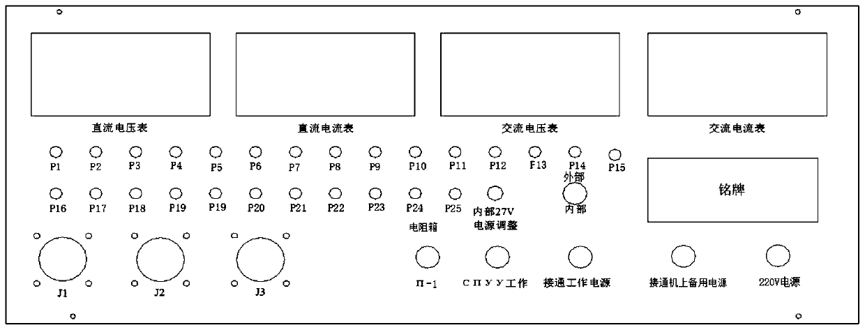
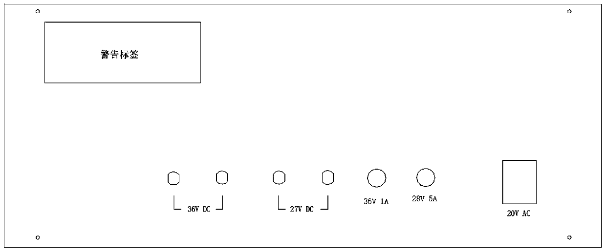
[0039] In order to overcome the problems existing in the test equipment of the tail rotor restraint system in the prior art, the embodiment of the present invention proposes a tail rotor restraint system that can not only perform single-piece inspection of each component, but also can be systematically debugged and tested. Propeller restraint system tester, the overall design structure is simple, and the electrical layout is reasonable.

[0040] The tail rotor...


PUM


Abstract

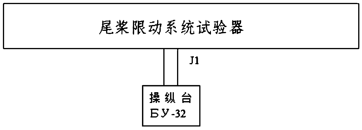
The invention relates to a tail rotor retaining system tester, comprising a tester body and a connecting cable, wherein the tester body comprises a chassis, a tester front panel and a tester rear panel; the tester rear panel provides an external power source; and the tester front panel is connected with the tail rotor retaining system through the connecting cable. According to the tail rotor retaining system tester provided in the invention, the design structure is simple, the electrical layout is reasonable, and in view of the tail rotor retaining system, single-piece test of a console as described in the specifications can be carried out, debugging on the whole set of the tail rotor retaining system as described in the specifications can also be realized on a test bench through simulating an on-board feeder, and test of AC current consumption and DC current consumption can be completed.

Description

technical field [0001] The invention relates to the technical field of debugging a helicopter tail rotor restraint system, in particular to a tail rotor restraint system tester. Background technique [0002] The tail rotor limiting system is used to automatically set the control limit of the rudder control mechanism (right rudder) according to the external temperature and pressure, so as to prevent the helicopter transmission system from being over-controlled. It is composed of five parts including measuring components, 6С2.553.009 feedback sensor, and П-1 temperature sensor. The infield can carry out single-piece inspection for each product of the tail rotor restraint system, and after passing the test, it can be installed on the machine, and the tail rotor restraint system can be jointly debugged and tested on the machine. [0003] The Chinese utility model patent with the publication number CN205574302U discloses a helicopter tail rotor test pitch control mechanism, incl...

Claims


Application Information

Patent Timeline
Patent Type & Authority Applications(China)
IPC IPC(8): G01M99/00
CPCG01M99/005
Inventor 吴万华杨爽
Owner 成都国营锦江机器厂
Learn More