
A walking motor speed control system with both manual and automatic gear shifting functions

A walking motor and speed control technology, which is applied to servo motors, servo motor components, fluid pressure actuators, etc., can solve problems such as potential safety hazards and crawler mechanical vibration, and achieve low maintenance difficulty, low processing cost, and internal flow. simple effect

Active Publication Date: 2020-04-17
JIANGSU ADVANCED CONSTR MASCH INNOVATION CENT LTD +1
View PDF2 Cites 0 Cited by
  • Summary
  • Abstract
  • Description
  • Claims
  • Application Information

AI Technical Summary

Problems solved by technology

[0007] The present invention discloses a hydraulic travel motor speed control system with manual shifting and automatic shifting functions, which effectively solves the safety hazards of the manual shifting valve when going uphill and the high and low speed of the automatic shifting valve under complex working conditions. The vibration problem of the crawler machinery caused by repeated switching between species improves the life of the travel motor and even the crawler machinery products, ensuring the safety of the crawler machinery; Requires additional components or systems attached to the system

Method used


Image

  • A walking motor speed control system with both manual and automatic gear shifting functions
  • A walking motor speed control system with both manual and automatic gear shifting functions
  • A walking motor speed control system with both manual and automatic gear shifting functions

Examples


Embodiment Construction

[0038] The present invention will be further described below in conjunction with the accompanying drawings. The following examples are only used to illustrate the technical solution of the present invention more clearly, but not to limit the protection scope of the present invention.

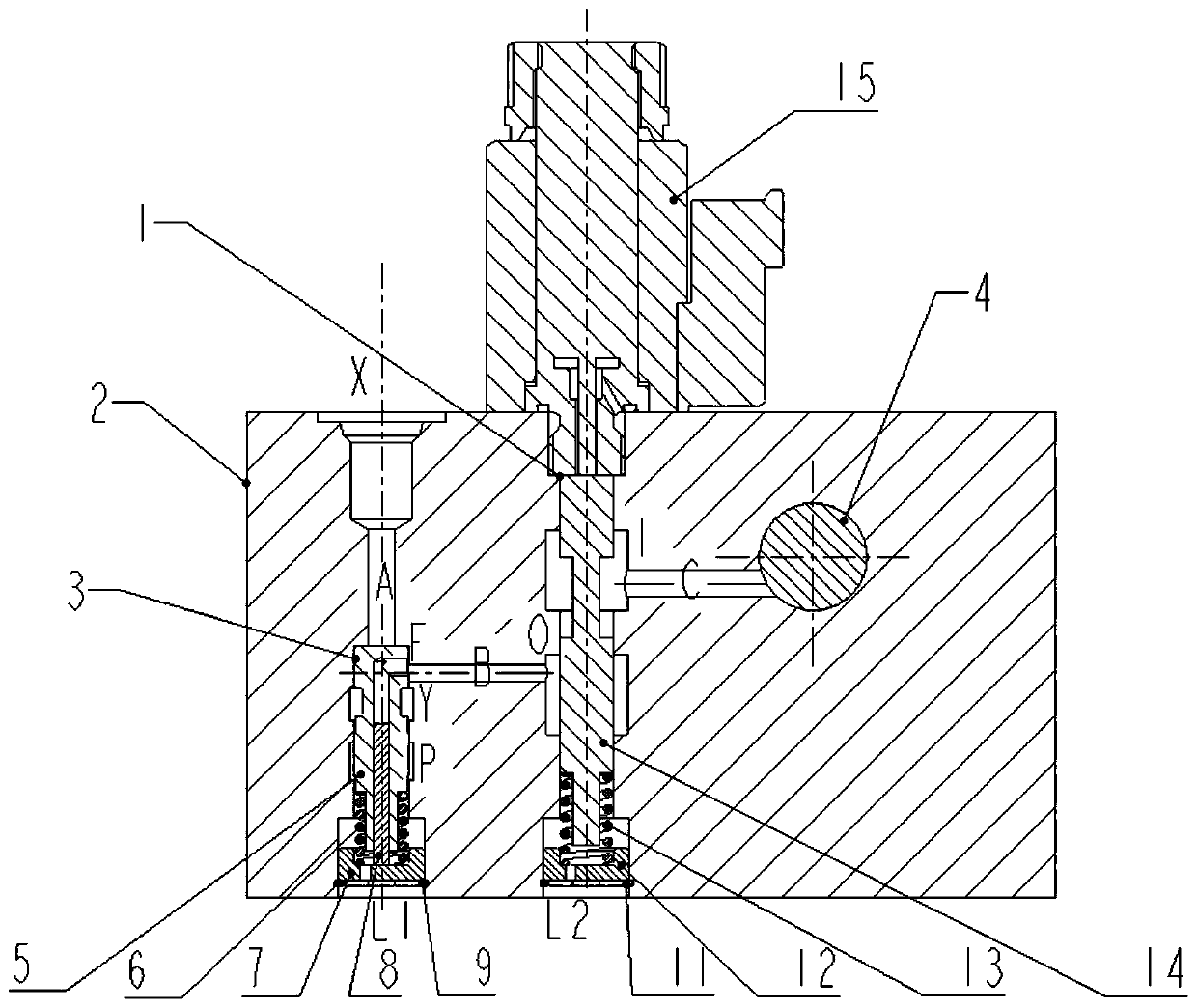
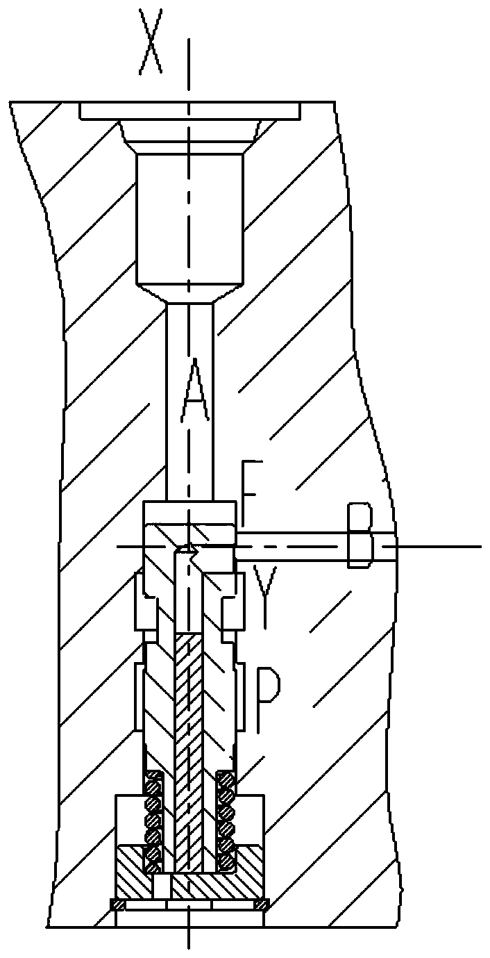
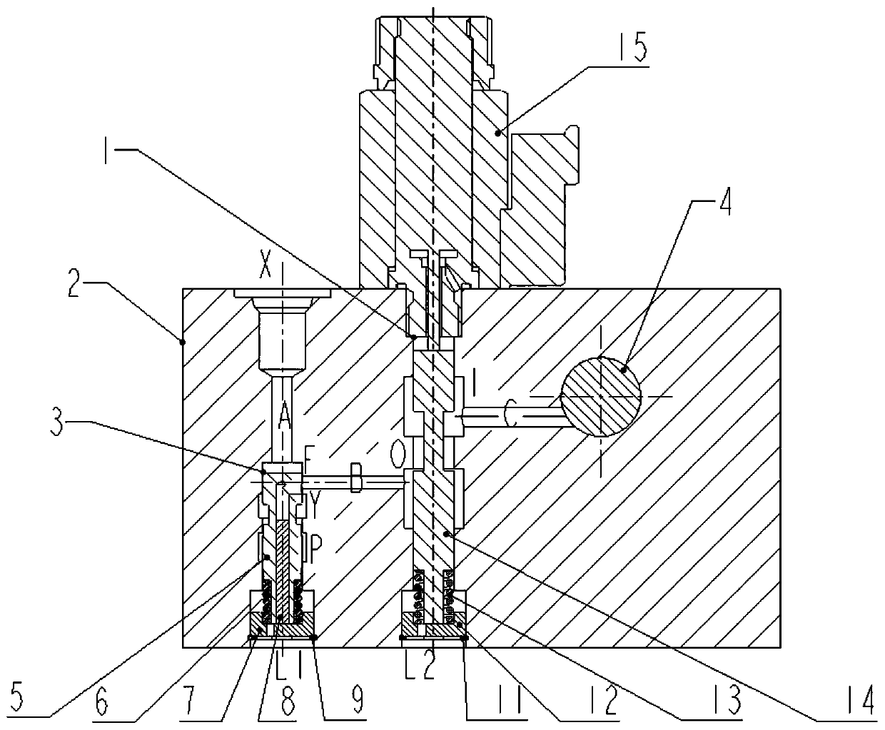
[0039] The invention patent adopts figure 1 with figure 2The structure shown includes motor end cover 2, shift valve 3, manual / automatic switching valve 1, balance valve 4, pilot oil circuit A, oil circuit B and oil circuit C. The shift valve 3 and the manual / automatic switch valve 1 are built inside the motor end cover 2, wherein the shift valve 3 is composed of a valve core 5, a return spring 6, a valve seat 7, a valve stem 8, and a retaining ring 9. One end is inserted into the valve seat 7 and can move along the valve seat 7. The return spring 6 is sleeved on the valve core 5, and is clamped by the shoulder on the valve core 5 and the valve seat 7. There is a vertical intersecting hole i...


PUM


Abstract

The invention discloses a travelling motor speed control system with both manual gearshift function and automatic gearshift function. The travelling motor speed control system with both manual gearshift function and automatic gearshift function comprises a gearshift valve, a manual / automatic switchover valve and a balance valve, wherein the gearshift valve is located at a first position or a second position through input pilot oil control; when the gearshift valve is located at the first position, a variable plunger cylinder of the motor is located at an initial position; when the gearshift valve is located at the second position, high-pressure oil in a shuttle valve of the motor is capable of entering the variable plunger cylinder of the motor; the manual / automatic switchover valve is correspondingly located at the first position or the second position through the power-on and power-off control of an electromagnet; when the manual / automatic switchover valve is located at the first position, a passage between a high-pressure input port and a high-pressure output port is blocked; and when the manual / automatic switchover valve is located at the second position, a high-pressure cavityof the balance valve forms communication with a pressure feedback port. The travelling motor speed control system with both manual gearshift function and automatic gearshift function is capable of solving the problems of potential safety hazards of the manual gearshift valve while going up a slope and the problem of mechanical vibration of a track, which is brought by the repeated switchover of the automatic gearshift valve between a high speed and a low speed under a complex working condition; and the system does not need to be added with additional components or systems, so that a simple structural form is achieved.

Description

technical field [0001] The invention relates to the hydraulic and mechanical fields, in particular to a shift valve for a hydraulic traveling motor. Background technique [0002] Various types of crawler machinery are widely used in civil, transportation, water conservancy projects, mining and mechanized construction of modern military projects. Its travel drive device is mostly composed of a swash plate type plunger motor with a star reducer, which is called a travel motor. Traveling motors generally require high-speed and low-speed operating modes, which are reflected on the plunger motor of the drive unit, that is, the plunger motor is required to have a two-stage speed change function. When the excavator is walking on slopes, muddy swamps, dragging and other working conditions, the travel motor is often required to provide greater driving torque, and the travel motor should always be in a "low-speed high-torque state". When the excavator is walking on a flat road or do...

Claims


Application Information

Patent Timeline
Patent Type & Authority Patents(China)
IPC IPC(8): F15B11/04F15B11/08F15B13/043
CPCF15B11/04F15B11/08F15B13/0402F15B2013/041F15B2211/75
Inventor 李正祥肖刚汤和荣
Owner JIANGSU ADVANCED CONSTR MASCH INNOVATION CENT LTD
Learn More